Typical Performance Characteristics (Continued)
DS012316-12
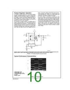
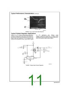
FIGURE 6. VOUT Load Current Step Response
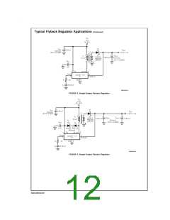
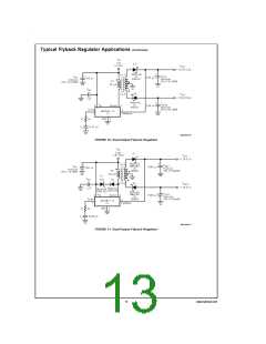
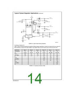
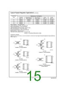
Typical Flyback Regulator Applications
Figures 7, 8, 9, 11, 12 show six typical flyback applications,
varying from single output to triple output. Each drawing con-
tains the part number(s) and manufacturer(s) for every com-
ponent except the transformer. For the transformer part
numbers and manufacturers names, see the table in Figure
13.
For
applications
with
different
output
voltages — requiring the LM2587-ADJ — or different output
configurations that do not match the standard configurations,
refer to the Switchers Made Simple software.
DS012316-13
FIGURE 7. Single-Output Flyback Regulator
11
www.national.com

 NSC [ National Semiconductor ]