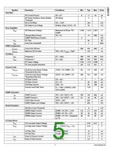
Symbol
HO Gate Driver
VOLH
Parameter
Conditions
Min
Typ
Max
0.27
Units
HO Low-state Output Voltage
HO High-state Output Voltage
IHO = 100mA
0.17
0.45
V
V
VOHH
IHO = -100mA, VOHH = VHB
VHO
–
HO Rise Time
C-load = 1000pF
C-load = 1000pF
VHO = 0V
19
13
1
ns
ns
A
HO High-side Fall Time
Peak HO Source Current
Peak HO Sink Current
HB to SW under-voltage
IOHH
IOLH
VHO = VCC
2.2
3
A
V
Switching Characteristics
LO Fall to HO Rise Delay
C-load = 0
C-load = 0
75
70
ns
ns
HO Fall to LO Rise Delay
Thermal
TSD
Thermal Shutdown
Rising
170
15
°C
°C
Thermal Shutdown Hysteresis
Junction to Ambient
40
°C/W
θJA
θJC
Junction to Case
4
°C/W
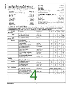
Note 1: Absolute Maximum Ratings indicate limits beyond which damage to the component may occur. Operating Ratings are conditions under which operation
of the device is guaranteed. Operating Ratings do not imply guaranteed performance limits. For guaranteed performance limits and associated test conditions,
see the Electrical Characteristics tables.
Note 2: The human body model is a 100pF capacitor discharged through a 1.5kΩ resistor into each pin. LO, HO and HB are rated at 1kV. 2kV rating for all pins
except VIN which is rated for 1.5kV.
Note 3: These pins must not exceed VIN.
www.national.com
6

 NSC [ National Semiconductor ]