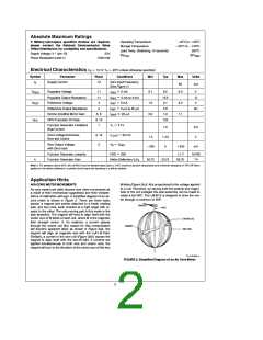
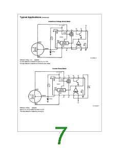
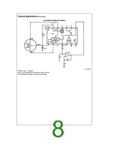
Application Hints (Continued)
TACHOMETER APPLICATION
A measure of the operating level of any motor or engine is
the rotational velocity of its output shaft. In the case of an
automotive engine the crankshaft speed is measured using
the units ‘‘revolutions per minute’’ (RPM). It is possible to
indirectly measure the speed of the crankshaft by using the
signal present on the engine’s ignition coil. The fundamental
frequency of this signal is a function of engine speed and
the number of cylinders and is calculated (for a four-stroke
engine) from the formula:
The charge pump circuit in Figure 7 can be operated in two
modes: constant input pulse width (C1 acts as a coupling
capacitor) and constant input duty cycle (C1 acts as a differ-
entiating capacitor). The transfer functions for these two
modes are quite diverse. However, deflection is always di-
rectly proportional to R2 and ripple is proportional to C2.
The following variables are used in the calculation of meter
deflection:
symbol description
e
f
n0/120
(Hz)
(5)
n
number of cylinders
e
e
where n number of cylinders, and 0 rotational velocity of
the crankshaft in RPM. From this formula the maximum fre-
quency normally expected (for an 8 cylinder engine turning
4500RPM) is 300 Hz. In certain specialized ignition systems
(motorcycles and some automobiles) where the coil wave-
e
0, 0
engine speed at redline and idle, RPM
pointer deflection at redline, degrees
charge pump input pulse width, seconds
peak to peak input voltages, volts
maximum desired ripple, degrees
function generator gain, degrees/volt
input frequency at redline and idle, Hz
IDLE
i
e
V
IN
f
form is operated at twice this frequency (
0/60). These
Di
systems are identified by the fact that multiple coils are used
in lieu of a single coil and distributor. Also, the coils have
two outputs instead of one.
k
f
f
IDLE
,
Where the NPN transistor and regulator are used to create a
e
grees (a typical pointer is about 3 degrees wide) depending
on meter damping and the input frequency.
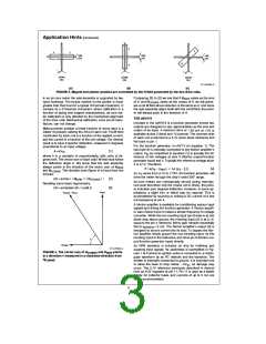
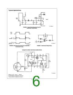
A typical automotive tachometer application is shown inFig-
ure 1. The coil waveform is filtered, squared and limited by
the RC network and NPN transistor. The frequency of the
pulse train at pin 9 is converted to a proportional voltage by
the Norton amplifier’s charge pump configuration. The igni-
tion circuit shown in Figure 5 is typical of automotive sys-
tems. The switching element ‘‘S’’ is opened and closed in
synchronism with engine rotation. When ‘‘S’’ is closed, en-
ergy is stored in Lp. When opened, the current in Lp diverts
from ‘‘S’’ into C. The high voltage produced in Ls when ‘‘S’’
is opened is responsible for the arcing at the spark plug.
The coil voltage (see Figure 6) can be used as an input to
the LM1819 tachometer circuit. This waveform is essentially
constant duty cycle. D4 rectifies this waveform thereby pre-
venting negative voltages from reaching the chip. C4 and
R5 form a low pass filter which attenuates the high frequen-
cy ringing, and R7 limits the input current to about 2.5mA.
R6 acts as a base bleed to shut the transistor OFF when
‘‘S’’ is closed. The collector is pulled up to the internal regu-
pulse V
IN
8.5V. Acceptable ripple ranges from 3 to 10 de-
The constant pulse width circuit is designed using the fol-
lowing equations:
V
IN
k
k
(1)
100 mA
3 mA
R1
10e
t
(2)
C
1
R
1
R i
120R i
1
1
e
e
e
(3)
(4)
R
2
f
V
ek
1
V n0ek
IN
IN
1
e
C
2
f
R Di
2
R Din0
2 IDLE
IDLE
The constant duty cycle equations are as follows:
t
R
R
3 kX
REG
4
x10
s
b
V
IN
R
REG
1
s
a
R )
1
C
1
e/10(R
REG
lator by R
pulse.
. The output at pin 9 is a clean rectangular
REG
e
e
i/425 C
f
R
i/3.54n0C
Z
1
1
e
C
2
425C /Di
1
Many ignition systems use magnetic, hall effect or optical
sensors to trigger a solid state switching element at ‘‘S.’’
These systems (see the LM1815) typically generate pulses
of constant width and amplitude suitable for driving the
charge pump directly.
e
The values in Figure
e
1
270 degrees,
were calculated with
e
n
4,
is
e
0
6000RPM,
i
e 1
ms,
V
IN
b
e
0.7V, and Di 3 degrees in the constant duty cycle
mode. For distributorless ignitions these same equations will
V
REG
f
apply if 0/60 is substituted for
.
4

 NSC [ National Semiconductor ]