Absolute Maximum Ratings
If Military/Aerospace specified devices are required,
please contact the National Semiconductor Sales
Office/Distributors for availability and specifications.
b a
40 C to 85 C
Operating Temperature
§
65 C to 150 C
§
b
b
Storage Temperature
§
§
Lead Temp. (Soldering, 10 seconds)
260 C
§
MIN
Supply Voltage, Va (pin 13)
20V
BV
20V
CEO
Power Dissipation (note 1)
1300 mW
e
e
25 C unless otherwise specified
Electrical Characteristics V
13.1V T
§
S
A
Symbol
Parameter
Supply Current
Pin(s)
Conditions
Min
Typ
Max
65
Units
I
13
Zero Input Frequency
(SeeFigure 1)
S
mA
e
e
e
e
j
V
Regulator Voltage
11
11
4
I
I
I
I
I
0 mA
8.1
1.9
0.9
8.5
13.5
2.1
8.9
V
X
REG
REG
REG
REF
REF
BIAS
Regulator Output Resistance
Reference Voltage
0 mA to 3 mA
0 mA
V
2.3
1.1
V
REF
Reference Output Resistance
Norton Amplifier Mirror Gain
NPN Transistor DC Gain
4
0 mA to 50 mA
20 mA
5.3
kX
5, 6
9, 10
1
1.0
h
125
FE
e
5.1V
Function Generator Feedback
Bias Current
V
1
1.0
mA
V
e
20 mA
Drive Voltage Extremes,
Sine and Cosine
2, 12
2
I
LOAD
g
g
4
4.5
e
V
REF
Sine Output Voltage
with Zero Input
V
8
b
a
350
350
0
mV
e
g
Function Generator Linearity
Function Generator Gain
FSD
305
1.7
%FSD
§
k
Meter Deflection/DV
50.75
53.75
56.75
/V
§
8
Note 1: For operation above 25 C, the LM1819 must be derated based upon a 125 C maximum junction temperature and a thermal resistance of 76 C/W which
§
§
§
applies for the device soldered in a printed circuit board and operating in a still-air ambient.
Application Hints
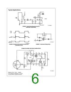
AIR-CORE METER MOVEMENTS
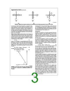
H fields(Figure 3(c)). H is proportional to the voltage applied
to a coil. Therefore, by varying both the polarity and magni-
tude of the coil voltages the axle assembly can be made to
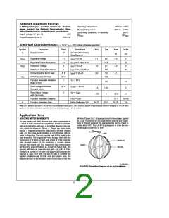
Air-core meters are often favored over other movements as
a result of their mechanical ruggedness and their indepen-
dence of calibration with age. A simplified diagram of an air-
core meter is shown in Figure 2. There are three basic
pieces: a magnet and pointer attached to a freely rotating
axle, and two coils, each oriented at a right angle with re-
spect to the other. The only moving part in this meter is the
axle assembly. The magnet will tend to align itself with the
vector sum of H fields of each coil, where H is the magnetic
rotate a full 360 . The LM1819 is designed to drive the me-
§
ter through a minimum of 305 .
§
field strength vector. If, for instance,
a current passes
through the cosine coil (the reason for this nomenclature
will become apparent later) as shown in Figure 3(a), the
magnet will align its magnetic axis with the coil’s H field.
Similarly, a current in the sine coil (Figure 3(b)) causes the
magnet to align itself with the sine H field. If currents are
applied simultaneously to both sine and cosine coils, the
magnet will turn to the direction of the vector sum of the two
TL/H/5263–2
FIGURE 2. Simplified Diagram of an Air Core Meter.
2

 NSC [ National Semiconductor ]