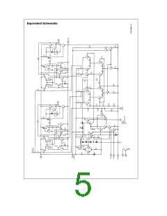
Application Hints (Continued)
TL/H/5263–3
(a)
(b)
(c)
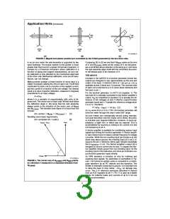
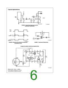
FIGURE 3. Magnet and pointer position are controlled by the H field generated by the two drive coils.
[ ]
[ ]
2 we see that if H
SINE
varies as the cosine of i, we will gener-
In an air-core meter the axle assembly is supported by two
nylon bushings. The torque exerted on the pointer is much
greater than that found in a typical d’Arsonval movement. In
contrast to a d’Arsonval movement, where calibration is a
function of spring and magnet characteristics, air-core me-
ter calibration is only affected by the mechanical alignment
of the drive coils. Mechanical calibration, once set at manu-
facture, can not change.
Comparing
of i, and H
3
to
varies as the sine
COSINE
ate a net H field whose direction is the same as i. And since
the axle assembly aligns itself with the net H field, the point-
er will always point in the direction of i.
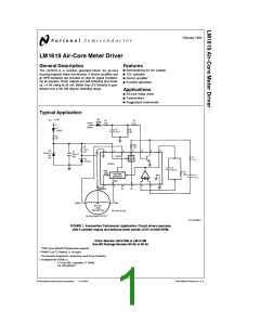
THE LM1819
Included in the LM1819 is a function generator whose two
outputs are designed to vary approximately as the sine and
cosine of an input. A minimum drive of 20 mA at 4V is
available at pins 2 (sine) and 12 (cosine). The common side
of each coil is returned to a 5.1V zener diode reference and
fed back to pin 1.
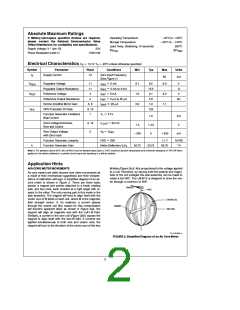
Making pointer position a linear function of some input is a
matter of properly ratioing the drive to each coil. The H field
contributed by each coil is a function of the applied current,
and the current is a function of the coil voltage. Our desired
result is to have i (pointer deflection, measured in degrees)
proportional to an input voltage:
g
g
j
For the function generator, k 54 /V (in equation 1). The
input (pin 8) is internally connected to the Norton amplifier’s
§
e
[ ]
1
i
kV
IN
[ ]
1 is actually the dif-
output. V as considered in equation
IN
where k is a constant of proportionality, with units of de-
grees/volt. The vector sum of each coils’ H field must follow
the deflection angle i. We know that the axle assembly
ference of the voltages at pins 8 (Norton output/function
generator input) and 4. Typically the reference voltage at pin
4 is 2.1V. Therefore,
always points in the direction of the vector sum of H
SINE
e
b
e
b
54 (V 2.1)
8
[ ]
4
i
k(V
V
REF
)
8
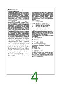
and H . This direction (see Figure 4) is found from the
COSINE
As V varies from 2.1V to 7.75V, the function generator will
8
formula:
drive the meter through the chip’s rated 305 range.
§
e
À
Ó
COSINE
[ ]
(i) arctan
H
/
H
2
l
SINE
l
Recalling some basic trigonometry,
l
l
Air-core meters are mechanically zeroed during manufac-
ture such that when only the cosine coil is driven, the point-
er indicates zero degrees deflection. However, in some ap-
plications a slight trim or offset may be required. This is
accomplished by sourcing or sinking a DC current of a few
microamperes at pin 4.
e
[ ]
3
(i) arctan(sin (i) / cos(i ))
A Norton amplifier is available for conditioning various input
signals and driving the function generator. A Norton amplifi-
er was chosen since it makes a simple frequency to voltage
converter. While the non-inverting input (pin 6) bias is at one
diode drop above ground, the inverting input (5) is at 2.1V,
equal to the pin 4 reference. Mirror gain remains essentially
e
flat to I
5 mA. The Norton amplifier’s output (8) is
MIRROR
designed to source current into its load. To bypass the Nor-
ton amplifier simply ground the non-inverting input, tie the
inverting input to the reference, and drive pin 8 (Norton out-
put/function generator input) directly.
An NPN transistor is included on chip for buffering and
squaring input signals. Its usefulness is exemplified in Fig-
ures 1 & 6 where an ignition pulse is converted to a rectan-
gular waveform by an RC network and the transistor. The
emitter is internally connected to ground. It is important not
TL/H/5263–4
FIGURE 4. The vector sum of H
and H
points
in a direction i measured in a clockwise direction from
COSINE
SINE
H
.
COSINE
b
to allow the base to drop below 5V , as damage may
dc
occur. The 2.1V reference previously described is derived
from an 8.5V regulator at pin 11. Pin 11 is used as a stable
supply for collector loads, and currents of up to 5 mA are
easily accommodated.
3

 NSC [ National Semiconductor ]