Random Lock Initialization and
Resynchronization
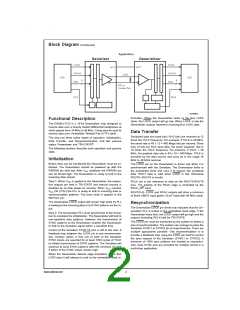
Powerdown
The Powerdown state is a low power sleep mode that can be
used to reduce power when there is no data to be trans-
ferred. Powerdown is entered when PWRDN and REN are
driven low on the Deserializer. In Powerdown, the PLL is
stopped and the outputs go into TRI-STATE, disabling load
current and also reducing supply current to the milliamp
range. To exit Powerdown, PWRDN is driven high.
The initialization and resynchronization methods described
in their respective sections are the fastest ways to establish
the link between the Serializer and Deserializer, however,
the DS92LV1212 can attain lock to a data stream without re-
quiring special SYNC patterns to be sent by the Serializer.
This allows the DS92LV1212 to be used in applications
where the Deserializer must operate “open-loop” and sup-
ports hot insertion into a running backplane. Because the
data stream is essentially random the time for the
DS92LV1212 to attain lock is variable and cannot be pre-
dicted. The primary constraint on the “random” lock time is
the initial phase relation when the Deserializer is powered
up. The data contained in the data stream can also affect
lock time. Typical lock times for random data have a mean of
570us and a max of 4.9ms.
Both the Serializer and Deserializer must re-initialize and re-
synchronize before data can be transferred. Initialization of
the Serializer takes 1024 TCLK cycles. The Deserializer will
initialize and assert LOCK high until it is locked to the Bus
LVDS clock.
TRI-STATE
For the Deserializer, TRI-STATE is entered when the REN
pin is driven low. This will TRI-STATE the receiver output
pins (ROUT0–ROUT9), LOCK and RCLK.
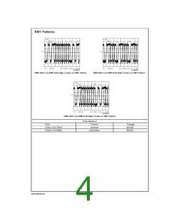
If a specific pattern is repetitive the Deserializer could be
misled into a “false lock” - falsely recognizing the data pat-
tern as the clocking bits. We refer to such a pattern as a re-
petitive multi-transition, RMT. This is when there is more than
one Low-High transition in a single clock cycle. This occurs
when any bit, except DIN 9, is held at a low state and the ad-
jacent bit is held high creating a 0-1 transition. In the worst
case the Deserializer could become locked to the data pat-
tern rather than the clock. Circuitry within the DS92LV1212
can detect that the possibility of “false lock” exists (by detect-
ing that there is more than 1 potential position for clocking
bits) and will prevent the LOCK* output from becoming ac-
tive until the potential “false lock” pattern changes. It is ex-
pected that the data will eventually change causing the De-
serializer to lose lock to the data pattern and continue
searching for the clock bits in the serial data stream. A
graphical representation of a few cases of RMT is shown
below. Please note that RMT applies to bits DIN0-DIN8.
3
www.national.com

 NSC [ National Semiconductor ]