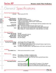
Miniature Audio/Video Pushbuttons
Series KP
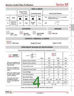
POLE & CIRCUIT
Plunger Position
Connected Terminals
Throw & Switch Schematic
( ) = Momentary
Normal
Down
Normal
Down
Note: Switch terminals “1” & “1a” are actually
marked on the switch.
Pole
Model
1 (COM)
KP0115A
KP0215A
Normally
Open
SP
OFF
(ON)
1-1a
SPST
1a
D
ACTUATION
HOUSING
C
N
S
K
Tactile
Nontactile
Tactile/Audible
Black only
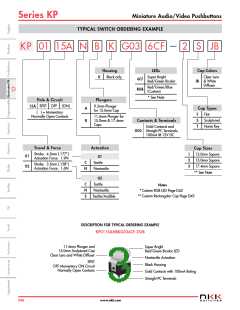
KP01 or KP02
KP01 or KP02
KP02 only
CONTACTS, TERMINALS, & RATING
G03
Gold Contacts
Straight PC Terminals
100mA @ 12V DC
SUPER BRIGHT BICOLOR LED SPECIFICATIONS
The electrical specifications shown are determined at a basic temperature of 25°C.
(–) L2
6CF
ATTENTION
Green
(+) COM
ELECTROSTATIC
SENSITIVE DEVICES
(–) L1
Red
Colors
Red
450
700
Green
820
Unit
mcd
mcd
Minimum Luminous Intensity
Standard Luminous Intensity
IV
IV
LEDs are an integral part of
the switch and are not avail-
able separately.
1100
30
25
Forward Peak Current
IFM
mA
(25 for amber)
(22 for amber)
LED circuit is isolated and
requires an external power
source.
Continuous Forward Current
Forward Voltage
IF
15
2.1
15
3.2
mA
V
VF
PD
If the source voltage exceeds
the rated voltage, a ballast
resistor is required.
Power Peak Dissipation
63
80
mW
V
Reverse Peak Voltage
VRM
λ
5
5
The resistor value can be
calculated by using the
formula in the Supplement
section.
Wavelength at Peak Emission
Current Reduction Rate Above 25°C
Ambient Temperature Range
630 ~ 640
0.40
520 ~ 535
0.36
nm
∆IF
mA/°C
°C
–25 ~ +50
Amber can be achieved by simultaneous illumination of Red & Green.
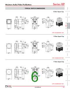
www.nkk.com
D39

 NKK [ NIHON KAIHEIKI INDUSTRY CO. LTD. ]