Nexperia
74AHC08-Q100; 74AHCT08-Q100
Quad 2-input AND gate
t
W
V
I
90 %
negative
pulse
V
V
V
M
M
10 %
0 V
t
t
r
f
t
t
f
r
V
I
90 %
positive
pulse
V
M
M
10 %
0 V
t
W
V
CC
V
CC
V
V
O
I
R
L
S1
G
open
DUT
R
T
C
L
001aad983
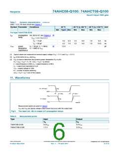
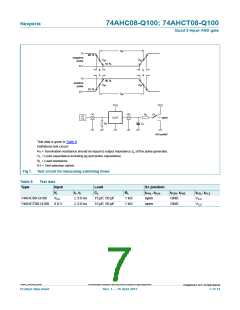
Test data is given in Table 9.
Definitions test circuit:
RT = Termination resistance should be equal to output impedance Zo of the pulse generator.
CL = Load capacitance including jig and probe capacitance.
RL = Load resistance.
S1 = Test selection switch.
Fig 7. Test circuit for measuring switching times
Table 9.
Type
Test data
Input
Load
S1 position
tPHL, tPLH
open
VI
tr, tf
CL
RL
tPZH, tPHZ
GND
tPZL, tPLZ
VCC
74AHC08-Q100
VCC
3.0 ns
3.0 ns
15 pF, 50 pF
15 pF, 50 pF
1 k
1 k
74AHCT08-Q100 3.0 V
open
GND
VCC
74AHC_AHCT08_Q100
All information provided in this document is subject to legal disclaimers.
©
Nexperia B.V. 2017. All rights reserved
Product data sheet
Rev. 1 — 16 April 2013
7 of 14

 NEXPERIA [ Nexperia ]