RoHS
RoHS
N-HFA15PB60
SEMICONDUCTOR
Nell High Power Products
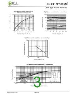
Fig.1 Maximum forward voltage drop vs.
Instantaneous forward current
Fig.2 Typical reverse current vs. reverse voltage
10000
100
10
T
= 150 °С
J
1000
100
10
T
= 125 °C
J
1
T
= 25 ºC
J
T
T
T
= 150 °С
= 125 °С
= 25 °С
J
J
J
0.1
0.01
1
1.0
0
100
200
300
400
500
600
1.2
1.4
1.6
1.8
2.0
2.2
2.4
Forward voltage drop (V), VFM
Reverse voltage (V), VR
Fig.3 Typical junction capacitance vs. reverse voltage
100
T
= 25 °С
J
10
10
100
1000
Reverse voltage (V), VR
Fig.4 Maximum thermal Impedance ZthJC characteristics
10
1
0.1
P
DM
t
1
D = 0.50
D = 0.20
D = 0.10
D = 0.05
D = 0.02
D = 0.01
t
2
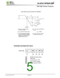
Notes:
1. Duty factor D = t1/ t 2
Single pulse
(thermal response)
2. Peak T = Pdm x ZthJC + Tc
0.01
0.00001
0.0001
0.001
0.01
0.1
1
Rectangular pulse duration (sec), t1
Page 3 of 6
www.nellsemi.com

 NELLSEMI [ NELL SEMICONDUCTOR CO., LTD ]