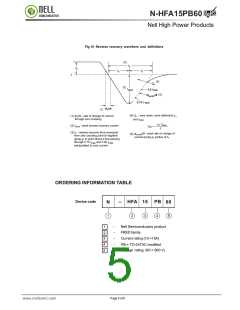
RoHS
RoHS
N-HFA15PB60
SEMICONDUCTOR
Nell High Power Products
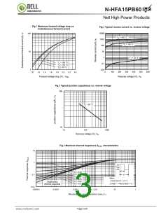
ELECTRICAL SPECIFICATIONS
(T = 25 ºC unless otherwise specified)
J
PARAMETER
SYMBOL
TEST CONDITIONS
MAX.
TYP.
UNITS
MIN.
Cathode to anode
breakdown voltage
-
-
VBR
IR = 100 µA
600
IF = 15 A
IF = 30 A
-
-
1.55
1.80
1.40
1.7
2.0
1.6
V
VFM
Maximum forward voltage
IF = 15 A, TJ = 125 ºC
-
VR = VR rated
TJ = 125°C, VR = VR rated
VR = 200V
-
-
1.0
400
25
10
1000
Maximum reverse
leakage current
IRM
µA
Junction capacitance
Series inductance
pF
nH
CT
LS
50
-
-
12
Measured lead to lead 5 mm from package body
-
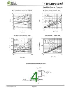
DYNAMIC RECOVERY CHARACTERISTICS PERLEG (T = 25 ºC unless otherwise specified)
J
PARAMETER
SYMBOL
TEST CONDITIONS
MIN.
MAX. UNITS
TYP.
IF = 0.5A, IR = 1.0A, IRR = 250mA (RG#1 CKT)
IF = 1.0 A, dIF/dt = -200 A/µs, VR =30 V, TJ = 25°C
-
-
30
22
trr
-
19
ns
Reverse recovery time
trr1
trr2
-
-
TJ = 25 ºC
42
74
60
TJ = 125 ºC
120
IF= 15A
dIF/dt = -200 A/µs
VR = 200 V
IRRM1
TJ = 25 ºC
-
-
6.0
4.0
Peak recovery current
A
IRRM2
Qrr1
TJ = 125 ºC
10
6.5
80
-
-
TJ = 25 ºC
TJ = 125 ºC
TJ = 25 ºC
TJ = 125 ºC
180
Reverse recovery charge
nC
Qrr2
220
188
160
600
-
dl(rec)M/dt1
dl(rec)M/dt2
-
Peak rate of fall of recovery
current during tb
A/µs
-
-
THERMAL - MECHANICAL SPECIFICATIONS PER LEG
PARAMETER
SYMBOL
TEST CONDITIONS
MIN.
TYP.
MAX.
UNITS
Lead temperature
Tlead
0.063'' from case (1.6 mm) for 10 s
–
300
°C
Junction to case,
single leg conduction
Junction to case,
both legs conducting
Thermal resistance,
junction to ambient
Thermal resistance,
case to heatsink
-
-
-
1.7
RthJC
-
40
40
-
K/W
RthJA
RthCS
Typical socket mount
–
-
Mounting surface, flat, smooth and greased
0.25
-
-
6.0
-
-
g
Weight
0.21
oz.
6.0
(5.0)
12
(10)
kgf . cm
(lbf . in)
Mounting torque
Marking device
-
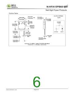
Case style TO-247AC (JEDEC)
HFA15PA60
Page 2 of 6
www.nellsemi.com

 NELLSEMI [ NELL SEMICONDUCTOR CO., LTD ]