µPD75304B,75306B,75308B
5.3 CLOCK OUTPUT CIRCUIT
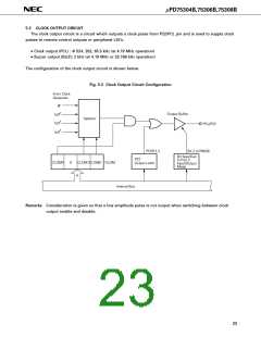
The clock output circuit is a circuit which outputs a clock pulse from P22/PCL pin and is used to supply clock
pulses to remote control outputs or peripheral LSI’s.
• Clock output (PCL) : Φ 524, 262, 65.5 kHz (at 4.19 MHz operation)
• Buzzer output (BUZ): 2 kHz (at 4.19 MHz or 32.768 kHz operation)
The configuration of the clock output circuit is shown below.
Fig. 5-2 Clock Output Circuit Configuration
From Clock
Generator
Φ
/23
/24
Output Buffer
f
X
X
Selector
f
PCL/P22
fX
/26
PORT2.2
Bit 2 of PMGB
Bit Specified
P22
Output Latch
In Port 2
Input/Output
Mode
CLOM3
0
CLOM1 CLOM0CLOM
4
Internal Bus
Remarks Consideration is given so that a low amplitude pulse is not output when switching between clock
output enable and disable.
23

 NEC [ NEC ]