µPD703100A-33, 703100A-40, 703101A-33, 703102A-33
18. RECOMMENDED SOLDERING CONDITIONS
This product should be soldered and mounted under the following recommended conditions.
For the details of the recommended soldering conditions, refer to the document Semiconductor Device Mounting
Technology Manual (C10535E).
For soldering methods and conditions other than those recommended below, contact your NEC sales
representative.
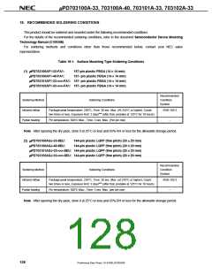
Table 18-1. Surface Mounting Type Soldering Conditions
(1) µPD703100AF1-33-FA1:
µPD703100AF1-40-FA1:
157-pin plastic FBGA (14 × 14 mm)
157- pin plastic FBGA (14 × 14 mm)
µPD703101AF1-33-×××-FA1: 157- pin plastic FBGA (14 × 14 mm)
µPD703102AF1-33-×××-FA1: 157- pin plastic FBGA (14 × 14 mm)
Recommended
Condition
Soldering Method
Soldering Conditions
Symbol
Infrared reflow
Partial heating
Package peak temperature: 230°C, Time: 30 sec. Max. (At 210°C or higher), Count:
two times or less, Exposure limit: 3 daysNote (after that, prebake at 125°C for 10 hours)
IR35-103-2
Pin temperature: 300°C Max., Time: 3 sec. Max. (Per pin row)
–
Note After opening the dry pack, store it at 25°C or less and 65% RH or less for the allowable storage period.
(2) µPD703100AGJ-33-8EU:
µPD703100AGJ-40-8EU:
144-pin plastic LQFP (fine pitch) (20 × 20 mm)
144-pin plastic LQFP (fine pitch) (20 × 20 mm)
µPD703101AGJ-33-×××-8EU: 144-pin plastic LQFP (fine pitch) (20 × 20 mm)
µPD703102AGJ-33-×××-8EU: 144-pin plastic LQFP (fine pitch) (20 × 20 mm)
Recommended
Condition
Soldering Method
Soldering Conditions
Symbol
Infrared reflow
Partial heating
Package peak temperature: 235°C, Time: 30 sec. Max. (at 210°C or higher), Count:
two times or less, Exposure limit: 3 daysNote (after that, prebake at 125°C for 10 hours)
IR35-103-2
Pin temperature: 300°C Max., Time: 3 sec. Max. (per pin row)
–
Note After opening the dry pack, store it at 25°C or less and 65% RH or less for the allowable storage period.
128
Preliminary Data Sheet U14168EJ2V0DS00

 NEC [ NEC ]