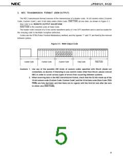
µPD6121, 6122
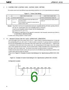
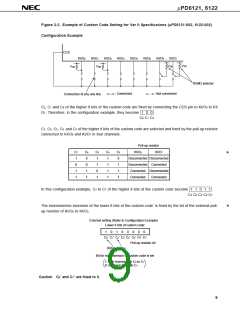
Figure 3-3. Example of Custom Code Setting for Ver II Specifications (µPD6121-002, 6122-002)
Configuration Example
CCS
KI/O
0
KI/O
1
KI/O
2
KI/O
3
KI/O
4
KI/O
5
KI/O
6
KI/O
7
V
DD
V
DD
V
DD
V
DD
ROM3 selector
: Connected
: Not connected
Connection of any one line
C2, C1 and C0 of the higher 8 bits of the custom code are fixed by connecting the CCS pin to KI/O0 to KI/
O7. Therefore, in the configuration example, they become 1 0 0 .
C0 C1 C2
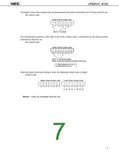
C7, C6, C5, C4 and C3 of the higher 8 bits of the custom code are selected and fixed by the pull-up resistor
connected to KI/O6 and KI/O7 in four channels.
Pull-up resistor
C7
C6
C5
C4
C3
KI/O
6
KI/O
7
*
*
1
0
1
1
0
0
1
1
1
1
0
1
1
1
1
1
0
1
1
1
Disconnected Disconnected
Disconnected Connected
Connected Disconnected
Connected
Connected
In this configuration example, C3 to C7 of the higher 8 bits of the custom code become 1 1 0 1 1 .
C3 C4 C5 C6 C7
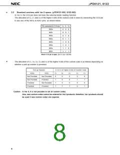
The inversion/non-inversion of the lower 8 bits of the custom code’ is fixed by the bit of the external pull-
up resistor of KI/O0 to KI/O5.
External setting (Refer to Configuration Example)
Lower 8 bits of custom code’
1
0
1
0
0
0
0
0
C6’
C0’ C1’ C2’ C
3’ C4’ C5’
C7’
Pull-up resistor bit
(KI/O
0
, KI/O )
2
Bit for non-inversion of custom code is set
1: Non-inversion for C to C
0
7
0: Inversion for C to C
0
7
Caution C6’ and C7’ are fixed to 0.
9

 NEC [ NEC ]