µPD6121, 6122
3. CUSTOM CODE (CUSTOM CODE, CUSTOM CODE’) SETTING
*
The custom code is set in two different ways depending on whether Ver I or Ver II specifications are employed.
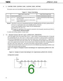
Figure 3-1. Custom Code Setting
Higher 8 bits of custom code
Fixed by external diode bit
Lower 8 bits of custom code’
Ver I
Fixed by external pull-up resistor bit
Ver II
C0, C1, C2 ... Fixed by connecting CCS pin and either one of
pins KI/O0 to KI/O7
Fixed by external pull-up resistor (KI/O0 to
KI/O5) bit
C3 to C7 ... Fixed by absence or presence of external pull-up
resistor for KI/O6, KI/O7
Remark The µPD6121-001 has Ver I specifications and is pin-compatible with the µPD1943G, and the µPD6122-
001 has Ver I specifications and is pin-compatible with the µPD6102G.
If used as pin-compatible products, please note the following points.
1 Connect the SEL pin to VDD.
2 Change the capacitance of the capacitor connected to the resonator connection pin (Refer to
9. ELECTRICAL SPECIFICATIONS).
A custom code setting example is shown below.
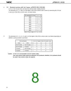
3.1 Standard versions with Ver I specs. (µPD6121-001, µPD6122-001)
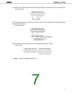
Each of the higher 8 bits of the custom code is set to “1” when a diode is connected between the CCS pin and
the corresponding KI/O pin, and is set to “0” when no diode is connected. If a pull-up resistor is connected to
the KI/O pin corresponding to one of the lower 8 bits of the custom code’, the bit is first set to “1”. Based on the
1’s information of the lower 8 bits of the custom code’, the corresponding bit of the higher 8 bits of the custom
code is then captured and not inverted. The non-inverted value is finally overwritten to the corresponding bit of
the lower 8 bits of the custom code’. The inverse occurs when no pull-up resistor is connected.
It follows from the above that the custom code can be set in 65,536 different ways depending on whether or not
a diode and/or pull-up resistor are present.
*
Please refer to Figure 3-2 Example of Custom Code Setting for Ver I Specifications (µPD6121-001, 6122-
001).
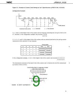
Figure 3-2. Example of Custom Code Setting for Ver I Specifications (µPD6121-001, 6122-001)
Configuration example
CCS
KI/O
0
KI/O
1
KI/O
2
KI/O
3
KI/O
4
KI/O
5
KI/O
6
KI/O
7
V
DD
V
DD
6

 NEC [ NEC ]