µPD178023, 178024
4. INTERRUPT FUNCTION
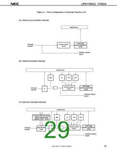
The µPD178023 and 178024 have the following three types and 17 sources of interrupts:
• Non-maskable : 1Note
• Maskable
• Software
: 16Note
: 1
Note Two types of watchdog interrupt sources (INTWDT), non-maskable and maskable, are available, and
either of them can be selected.
Table 4-1. Interrupt Sources
Vector
Table
Basic
Interrupt Source
Trigger
Default
PriorityNote 1
Internal/
External
Interrupt Type
Non-maskable
Maskable
Configuration
TypeNote 2
Name
Address
–
0
INTWDT Overflow of watchdog timer
(when watchdog timer mode 1 is selected)
INTWDT Overflow of watchdog timer
(when interval timer mode is selected)
Internal
0004H
(A)
(B)
(C)
1
2
INTP0
INTP1
INTP2
INTP3
INTP4
INTKY
INTIIC0
Pin input edge detection
External 0006H
0008H
3
000AH
4
000CH
5
000EH
6
Detection of key input of port 4
Internal
0010H
0012H
0014H
0016H
0018HNote 3
001AH
001CH
(B)
7
End of transfer by serial interface IIC0
8
INTBTM0 Generation of basic timer match signal
9
INTAD3
–
End of conversion by A/D converter
–
10
11
12
–
–
INTCSI3 End of transfer by serial interface SIO3
Internal
(B)
INTTM50 Generation of coincidence signal of 8-bit
timer/event counter 50
13
INTTM51 Generation of coincidence signal of 8-bit
timer/event counter 51
001EH
14
15
16
–
INTSER0 Reception error of serial interface UART0
0020H
0022H
0024H
003EH
INTSR0
INTST0
BRK
End of reception by serial interface UART0
End of transmission by serial interface UART0
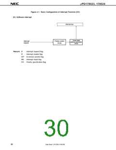
Execution of BRK instruction
Software
–
(D)
Notes 1. If two or more maskable interrupts occur at the same time, they are acknowledged or kept pending
according to their default priorities. The default priority 0 is the highest, while 16 is the lowest.
2. (A) to (D) under the heading Basic Configuration Type corresponds to (A) to (D) in Figure 4-1.
3. There are no interrupt sources corresponding to vector addresses 0018H.
28
Data Sheet U14126EJ1V0DS00

 NEC [ NEC ]