■ NOTICE
(1) Capacitive load
If the load is capacitive, an inrush current to charge the load with poses a problem . In this case, a current-lim iting
resistor or surge suppressor coil is connected in series to the contacts to suppress the peak current.
(2) Clinching term inals
To secure the relay temporarily to a printed circuit board for soldering, particular terminals are allowed to be clinched
within a particular angle. other term inals, never clinched.
The term inal num bers and the angle for clinching of each series are as follows.
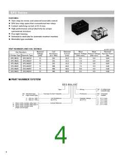
1) No.4 and no.5 term inals to 45° m axim um for H bridge type of EN2 and EP2
2) No.5 and no.9 term inals to 45° m axim um for separate type of EN2 and EP2
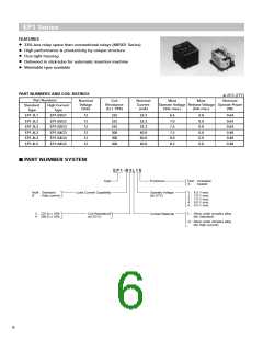
3) No.4 and no.5 term inals to 45° m axim um for EP1
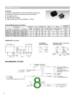
4) No.1, 4 and no.5 term inals to 45° m axim um for MR301
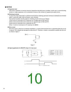
(3) Drive circuit
Since the coil of a relay has an inductive im pedance, a counter electrom otive force is generated when the circuit
is opened. This voltage m ay dam age the relay driver IC. Therefore, a diode is connected in parallel with the coil,
as shown in figure 1.
Figure 1
(4) Typical application for EN2/ EP2 relays (H bridge type)
MOTOR
STOP
Tr1
off
on
Tr2
off
off
on
FORWARD
REVERSE
M
off
Tr1
Tr2
100 ms min.
10

 NEC [ NEC ]