• This PDF catalog is downloaded from the website of Murata Manufacturing co., ltd. Therefore, it’s specifications are subject to change or our products in it may be discontinued without advance notice. Please check with our
• Please read rating and !CAUTION (for storage, operating, rating, soldering, mounting and handling) in this catalog to prevent smoking and/or burning, etc.
!Note
!Note
C02E.pdf
sales representatives or product engineers before ordering.
• This catalog has only typical specifications because there is no space for detailed specifications. Therefore, please approve our product specifications or transact the approval sheet for product specifications before ordering0. 9.9.18
• This PDF catalog has only typical specifications because there is no space for detailed specifications. Therefore, please approve our product specifications or transact the approval sheet for product specifications before ordering.
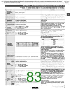
LLL/LLA/LLM Series Specifications and Test Methods (1)
In case Non "*" is added in PNs table, please refer to LLL/LLA/LLM Series Specifications and Test Methods (1).
Continued from the preceding page.
In case "*" is added in PNs table, please refer to LLL/LLA/LLM Series Specifications and Test Methods (2).
Specifications
No.
Item
Test Method
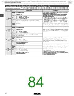
Fix the capacitor to the supporting jig in the same manner and
under the same conditions as (10).
Perform the five cycles according to the four heat treatments
listed in the following table. Let sit for 24T2 hours at room
temperature, then measure.
Appearance
No marking defects
Within T7.5%
Capacitance
Change
3
W.V.: 25V min.; 0.025 max.
W.V.: 16V/10V max.; 0.035 max.
W.V.: 6.3V max.; 0.05 max.
D.F.
I.R.
Step
1
2
3
4
Temperature
Cycle
Min. Operating
Temp. –3
Max. Operating
Temp. –0
Room
Temp.
Room
Temp.
14
+0
+3
Temp. (°C)
Time (min.)
More than 10,000MΩ or 500Ω · F (Whichever is smaller)
30T3
30T3
2 to 3
2 to 3
• Initial measurement.
Perform a heat treatment at 150
let sit for 24T2 hours at room temperature. Perform the initial
Dielectric
Strength
+0
–10
No failure
°C for one hour and then
measurement.
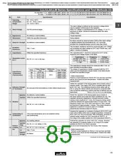
Appearance
No marking defects
Capacitance
Change
Within T12.5%
Humidity
15 (Steady
State)
Sit the capacitor at 40T2°C and 90 to 95% humidity for 500T12
hours. Remove and let sit for 24T2 hours at room temperature,
then measure.
W.V.: 10V min.; 0.05 max.
W.V.: 6.3V max.; 0.075 max.
D.F.
I.R.
More than 1,000MΩ or 50Ω · F (Whichever is smaller)
Appearance
No marking defects
Capacitance
Change
Within T12.5%
Apply the rated voltage at 40T2°C and 90 to 95% humidity for
500T12 hours. Remove and let sit for 24T2 hours at room
temperature, then measure. The charge/discharge current is
less than 50mA.
Humidity
Load
16
W.V.: 10V min.; 0.05 max.
W.V.: 6.3V max.; 0.075 max.
D.F.
More than 500MΩ or 25Ω · F
(Whichever is smaller)
I.R.
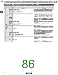
Apply 200% of the rated voltage for 1000T12 hours at the
maximum operating temperature T3°C. Let sit for 24T2 hours
at room temperature, then measure. The charge/discharge
current is less than 50mA.
Appearance
No marking defects
Capacitance
Change
Within T12.5%
High
17 Temperature
Load
W.V.: 10V min.; 0.05 max.
W.V.: 6.3V max.; 0.075 max.
D.F.
I.R.
•Initial measurement.
Apply 200% of the rated DC voltage for one hour at the
maximum operating temperature T3°C. Remove and let sit for
24T2 hours at room temperature.
More than 1,000MΩ or 50Ω · F
(Whichever is smaller)
Perform initial measurement.
82

 MURATA [ muRata ]