• This PDF catalog is downloaded from the website of Murata Manufacturing co., ltd. Therefore, it’s specifications are subject to change or our products in it may be discontinued without advance notice. Please check with our
• Please read rating and !CAUTION (for storage, operating, rating, soldering, mounting and handling) in this catalog to prevent smoking and/or burning, etc.
!Note
!Note
C02E.pdf
sales representatives or product engineers before ordering.
• This catalog has only typical specifications because there is no space for detailed specifications. Therefore, please approve our product specifications or transact the approval sheet for product specifications before ordering0. 9.9.18
• This PDF catalog has only typical specifications because there is no space for detailed specifications. Therefore, please approve our product specifications or transact the approval sheet for product specifications before ordering.
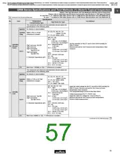
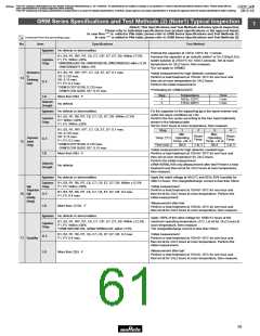
GRM Series Specifications and Test Methods (2) (Note1) Typical Inspection
GRM Series Specifications and Test Methods (2) (Note1) Typical Inspection
1
(Note1) This Specifications and Test Methods indicates typical inspection.
Please refer to individual specifications (our product specifications or the approval sheet).
In case Non "*" is added in PNs table, please refer to GRM Series Specifications and Test Methods (1).
Continued from the preceding page.
In case "*" is added in PNs table, please refer to GRM Series Specifications and Test Methods (2).
No.
Item
Specifications
Test Method
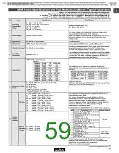
Appearance
No defects or abnormalities
Preheat the capacitor at 120 to 150°C for 1 minute.
Immerse the capacitor in an eutectic solder* or Sn-3.0Ag-0.5Cu
solder solution at 270±5°C for 10±0.5 seconds. Set at room
temperature for 24±2 hours, then measure.
B1, B3, R1, R6*, R7, C6, C7, C8*, E7, D7, D8: Within ±7.5%
F1, F5: Within ±20%
Capacitance
Change
*GRM188R6 0J/0G 106, GRM188C80E106, GRM219R60G226: within ±12.5%
GRM155R60G475: Within ±15%
*Do not apply to GRM02.
Resistance
to
Soldering
Heat
B1, B3, R1, R6*, R7*, C7, C8, E7, D7: 0.1 max.
C6: 0.125 max.
D8: 0.15 max.
F1, F5: 0.2 max.
*GRM31CR71E106: 0.125 max.
GRM31CR6 0J/0G 107: 0.15 max.
•Initial measurement for high dielectric constant type
Perform a heat treatment at 150+0/–10°C for one hour and
then set at room temperature for 24±2 hours.
Perform the initial measurement.
14
D.F.
I.R.
*Preheating for GRM32/43/55
Step
1
2
Temperature
100 to 120°C
170 to 200°C
Time
1 min.
1 min.
More than 50Ω · F
No defects
Dielectric
Strength
Appearance
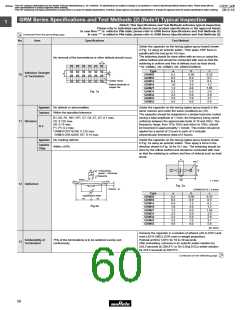
No defects or abnormalities
Fix the capacitor to the supporting jig in the same manner and
under the same conditions as (10).
Perform the five cycles according to the four heat treatments
shown in the following table.
B1, B3, R1, R6, R7, C6, C7, C8, D7, D8: Within ±7.5%
E7: Within ±30%
F1, F5: Within ±20%
Capacitance
Change
Set for 24±2 hours at room temperature, then measure.
B1, B3, R1, R6*, R7*, C7, C8, E7, D7: 0.1 max.
C6: 0.125 max.
D8: 0.15 max.
Step
1
2
3
4
Min.
Max.
Operating
Temp. +3/–0
Room
Temp.
Room
Temp.
Temperature
Temp. (°C) Operating
D.F.
I.R.
F1, F5: 0.2 max.
Temp. +0/–3
15 Sudden
Change
*GRM31CR71E106: 0.125 max.
GRM31CR6 0J/0G 107: 0.15 max.
Time (min.)
30±3
2 to 3
30±3
2 to 3
•Initial measurement for high dielectric constant type
More than 50Ω · F
Perform a heat treatment at 150+0/–10°C for one hour and
then set at room temperature for 24±2 hours.
Perform the initial measurement.
Dielectric
Strength
GRM188R60J106 only Measurement after test Perform a heat
treatment and then let sit for 24±2 hours at room temperature,
then measure.
No defects
Appearance
No defects or abnormalities
Apply the rated voltage at 40±2°C and 90 to 95% humidity for
500±12 hours. The charge/discharge current is less than 50mA.
Capacitance
Change
B1, B3, R1, R6, R7, C6, C7, C8, E7, D7, D8: Within ±12.5%
F1, F5: Within ±30%
High
•Initial measurement
Temperature
16 High
Humidity
Perform a heat treatment at 150+0/–10°C for one hour and
then let sit for 24±2 hours at room temperature. Perform the
initial measurement.
B1, B3, R1, R6, R7, C6, C7, C8, E7, D7, D8: 0.2 max.
F1, F5: 0.4 max.
D.F.
(Steady)
•Measurement after test
Perform a heat treatment at 150+0/–10°C for one hour and
then let sit for 24±2 hours at room temperature, then measure.
I.R.
More than 12.5Ω · F
Appearance
No defects or abnormalities
Apply 150% of the rated voltage for 1000±12 hours at the
maximum operating temperature ±3°C. Let sit for 24±2 hours at
room temperature, then measure.
B1, B3, R1, R6*, R7, C6, C7, C8*, E7, D7, D8: Within ±12.5%
F1, F5: Within ±30%
*GRM188C80E106, GRM219R60G226: within ±15%
Capacitance
Change
The charge/discharge current is less than 50mA.
B1, B3, R1, R6, R7, C6, C7, C8, E7, D7, D8: 0.2 max.
F1, F5: 0.4 max.
•Initial measurement
D.F.
I.R.
17 Durability
Perform a heat treatment at 150+0/–10°C for one hour and
then let sit for 24±2 hours at room temperature. Perform the
initial measurement.
•Measurement after test
Perform a heat treatment at 150+0/–10°C for one hour and
then let sit for 24±2 hours at room temperature, then measure.
More than 25Ω · F
59

 MURATA [ muRata ]