• This PDF catalog is downloaded from the website of Murata Manufacturing co., ltd. Therefore, it’s specifications are subject to change or our products in it may be discontinued without advance notice. Please check with our
• Please read rating and !CAUTION (for storage, operating, rating, soldering, mounting and handling) in this catalog to prevent smoking and/or burning, etc.
!Note
!Note
C02E.pdf
sales representatives or product engineers before ordering.
• This catalog has only typical specifications because there is no space for detailed specifications. Therefore, please approve our product specifications or transact the approval sheet for product specifications before ordering0. 9.9.18
• This PDF catalog has only typical specifications because there is no space for detailed specifications. Therefore, please approve our product specifications or transact the approval sheet for product specifications before ordering.
GRM Series Specifications and Test Methods (2) (Note1) Typical Inspection
GRM Series Specifications and Test Methods (2) (Note1) Typical Inspection
1
(Note1) This Specifications and Test Methods indicates typical inspection.
Please refer to individual specifications (our product specifications or the approval sheet).
In case Non "*" is added in PNs table, please refer to GRM Series Specifications and Test Methods (1).
Continued from the preceding page.
In case "*" is added in PNs table, please refer to GRM Series Specifications and Test Methods (2).
No.
Item
Specifications
Test Method
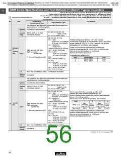
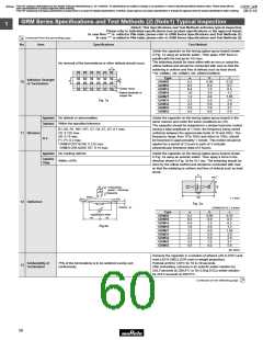
Solder the capacitor on the test jig (glass epoxy board) shown
in Fig. 1a using an eutectic solder. Then apply 10N* force in
parallel with the test jig for 10±1sec.
The soldering should be done either with an iron or using the
reflow method and should be conducted with care so that the
soldering is uniform and free of defects such as heat shock.
*1N: GRM02, 2N: GRM03, 5N: GRM15/GRM18
No removal of the terminations or other defects should occur.
c
Type
GRM02
a
b
c
Adhesive Strength
of Termination
10
0.2
0.3
0.4
1.0
1.2
2.2
2.2
3.5
4.5
0.56
0.9
1.5
3.0
4.0
5.0
5.0
7.0
8.0
0.23
0.3
0.5
1.2
1.65
2.0
2.9
3.7
5.6
GRM03
GRM15
GRM18
GRM21
GRM31
GRM32
GRM43
GRM55
Solder resist
Baked electrode or
copper foil
Fig. 1a
Appearance
Capacitance
No defects or abnormalities
Within the specified tolerance
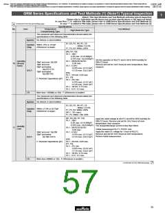
Solder the capacitor on the test jig (glass epoxy board) in the
same manner and under the same conditions as (10).
The capacitor should be subjected to a simple harmonic motion
having a total amplitude of 1.5mm, the frequency being varied
uniformly between the approximate limits of 10 and 55Hz. The
frequency range, from 10 to 55Hz and return to 10Hz, should
be traversed in approximately 1 minute. This motion should be
applied for a period of 2 hours in each of 3 mutually
B1, B3, R1, R6*, R7*, C7, C8, E7, D7: 0.1 max.
C6: 0.125 max.
D8: 0.15 max.
F1, F5: 0.2 max.
*GRM31CR71E106: 0.125 max.
GRM31CR6 0J/0G 107: 0.15 max.
11 Vibration
D.F.
perpendicular directions (total of 6 hours).
Appearance
No marking defects
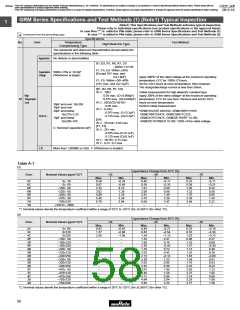
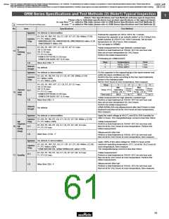
Solder the capacitor on the test jig (glass epoxy board) shown
in Fig. 2a using an eutectic solder. Then apply a force in the
direction shown in Fig. 3a for 5±1 sec. The soldering should be
done by the reflow method and should be conducted with care
so that the soldering is uniform and free of defects such as heat
shock.
Capacitance
Change
Within ±10%
b
ø4.5
c
20
Pressurizing
speed : 1.0mm/sec.
50
Pressurize
a
R230
100
t: 1.6mm
12 Deflection
Fig. 2a
Flexure : V1
(GRM02/03/15: t: 0.8mm)
Type
GRM02
a
b
c
Capacitance meter
0.2
0.3
0.4
1.0
1.2
2.2
2.2
3.5
4.5
0.56
0.9
1.5
3.0
4.0
5.0
5.0
7.0
8.0
0.23
0.3
0.5
1.2
1.65
2.0
2.9
3.7
5.6
45
45
GRM03
GRM15
GRM18
GRM21
GRM31
GRM32
GRM43
GRM55
Fig.3a
(in mm)
Immerse the capacitor in a solution of ethanol (JIS-K-8101) and
rosin (JIS-K-5902) (25% rosin in weight proportion).
Preheat at 80 to 120°C for 10 to 30 seconds.
After preheating, immerse in an eutectic solder solution for
2±0.5 seconds at 230±5°C or Sn-3.0Ag-0.5Cu solder solution
for 2±0.5 seconds at 245±5°C.
Solderability of
Termination
75% of the terminations is to be soldered evenly and
continuously.
13
Continued on the following page.
58

 MURATA [ muRata ]