• This PDF catalog is downloaded from the website of Murata Manufacturing co., ltd. Therefore, it’s specifications are subject to change or our products in it may be discontinued without advance notice. Please check with our
• Please read rating and !CAUTION (for storage, operating, rating, soldering, mounting and handling) in this catalog to prevent smoking and/or burning, etc.
!Note
!Note
C02E.pdf
sales representatives or product engineers before ordering.
• This catalog has only typical specifications because there is no space for detailed specifications. Therefore, please approve our product specifications or transact the approval sheet for product specifications before ordering0. 9.9.18
• This PDF catalog has only typical specifications because there is no space for detailed specifications. Therefore, please approve our product specifications or transact the approval sheet for product specifications before ordering.
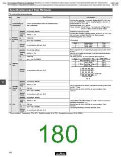
Specifications and Test Methods
Continued from the preceding page.
Specifications
No.
Item
Test Method
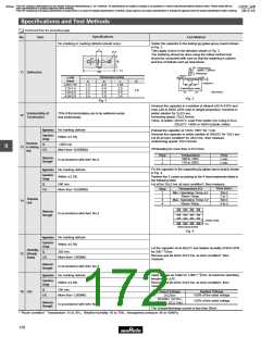
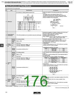
Solder the capacitor to the testing jig (glass epoxy board) shown
in Fig. 2.
No cracking or marking defects should occur.
Then apply a force in the direction shown in Fig. 3.
The soldering should be done using the reflow method and
should be conducted with care so that the soldering is uniform
and free of defects such as heat shock.
b
φ4.5
d
c
50
Pressurizing
20
a
speed : 1.0mm/s
t : 1.6
Pressurize
100
R230
11 Deflection
Dimension (mm)
LZW
(mm)
a
b
c
d
Flexure=1
1.6Z0.80
2.0Z1.25
3.2Z1.60
3.2Z2.50
4.5Z3.20
5.7Z5.00
1.0
1.2
2.2
2.2
3.5
4.5
3.0
4.0
5.0
5.0
7.0
8.0
1.25
1.65
2.05
2.95
3.75
5.65
Capacitance meter
45 45
(in mm)
1.0
Fig. 3
Fig. 2
Immerse the capacitor in a solution of ethanol (JIS-K-8101) and
rosin (JIS-K-5902) (25% rosin in weight proportion).
Immerse in solder solution for 2T0.5 sec.
Solderability of
Termination
12
75% of the terminations are to be soldered evenly and continuously.
Immersing speed: 25T2.5mm/s
Temp. of solder: 245T5°C Lead Free Solder (Sn-3.0Ag-0.5Cu)
235T5°C H60A or H63A Eutectic Solder
*
Preheat the capacitor at 120 to 150D for 1 min.
Appearance
No marking defects
Within T10%
Immerse the capacitor in solder solution at 260T5D for 10T1
sec. Let sit at room condition* for 24T2 hrs., then measure.
#Immersing speed: 25T2.5mm/s
Capacitance
Change
#Pretreatment
Perform a heat treatment at 150
let sit for 24T2 hrs. at room condition*.
D.F.
I.R.
0.025 max.
W00
Y10
Resistance
13 to Soldering
Heat
D for 60T5 min. and then
CU0.01µF: More than 100MΩ • µF
CF0.01µF: More than 10,000MΩ
10
*Preheating for more than 3.2Z2.5mm
Dielectric
Strength
Step
1
2
Temperature
100 to 120D
170 to 200D
Time
1 min.
1 min.
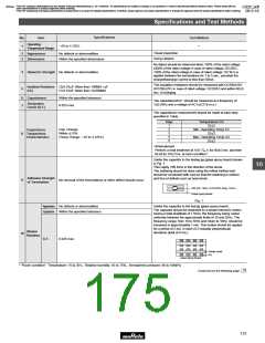
In accordance with item No.4
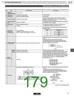
Fix the capacitor to the supporting jig (glass epoxy board) shown
in Fig. 4.
Perform the 5 cycles according to the 4 heat treatments listed in
the following table.
Appearance
No marking defects
Within T7.5%
0.025 max.
Capacitance
Change
D.F.
I.R.
Let sit for 24T2 hrs. at room condition*, then measure.
Time (min.)
30T3
2 to 3
30T3
2 to 3
Temperature (D)
Min. Operating Temp.T3
Room Temp.
Max. Operating Temp.T2
Room Temp.
Step
CU0.01µF: More than 100MΩ • µF
CF0.01µF: More than 10,000MΩ
1
2
3
4
Temperature
14
#Pretreatment
Perform a heat treatment at 150
Cycle
W00
Y10
D for 60T5 min. and then
let sit for 24T2 hrs. at room condition*.
Dielectric
Strength
In accordance with item No.4
Solder resist
Cu
Glass Epoxy Board
Fig. 4
Appearance
No marking defects
Within T15%
0.05 max.
Let the capacitor sit at 40T2D and relative humidity of 90 to 95%
W24
Capacitance
Change
for 500
hrs.
Y00
Remove and let sit for 24T2 hrs. at room condition*, then
measure.
Humidity
15 (Steady
State)
D.F.
I.R.
CU0.01µF: More than 10MΩ • µF
CF0.01µF: More than 1,000MΩ
#Pretreatment
Perform a heat treatment at 150
W00
Y10
D for 60T5 min. and then
let sit for 24T2 hrs. at room condition*.
Dielectric
Strength
In accordance with item No.4
* "Room condition" Temperature: 15 to 35D, Relative humidity: 45 to 75%, Atmospheric pressure: 86 to 106kPa
Continued on the following page.
174

 MURATA [ muRata ]