■AEC-Q200 Murata Standard Specification and Test Methods
No
AEC-Q200 Test Item
Specification.
AEC-Q200 Test Method
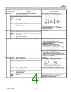
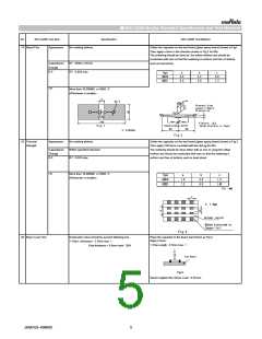
14 Thermal Shock
The measured and observed characteristics should satisfy the
specifications in the following table.
No marking defects
Solder the capacitor on the test board (glass epoxy board).
Perform the 300 cycles according to the two heat treatments listed
in the following table(Maximum transfer time is 20s).
Set for 24±2h at room temperature, then measure.
Appearance
Capacitance
Change
D.F.
R7 : Within ±10.0%
R7 : 0.025 max.
Step
1
2
-55+0/-3
(for R7)
125+3/-0
(for R7)
Temp.(℃)
Time
(min.)
15±3
15±3
I.R.
More than 10,000MΩ or 500Ω・F
(Whichever is smaller)
・ Initial measurement for high dielectric constant type
Perform a heat treatment at 150+0/-10 ℃ꢀfor 1h and then set
for 24±2h at room temperature.
Perform the initial measurement.
15 ESD
Appearance
Capacitance
Change
No marking defects
Per AEC-Q200-002
Within the specified tolerance
D.F.
R7 : 0.025 max.
I.R.
More than 10,000MΩ or 500Ω・F
(Whichever is smaller)
95% of the terminations is to be soldered evenly and continuously.
16 Solderability
(a) Preheat at 155℃ for 4h. After preheating, immerse the
ꢀꢀcapacitor in a solution of ethanol(JIS-K-8101) and rosin (JIS-K-
ꢀꢀ5902) (25% rosin in weight proportion). Immerse in
ꢀSn-3.0Ag-0.5Cu solder solution at 245±5℃ or an eutectic solder
solution at 235±5℃ for 5+0/-0.5s.
(b) should be placed into steam aging for 8h±15min.
ꢀꢀAfter preheating, immerse the capacitor in a solution of
ꢀꢀethanol(JIS-K-8101) and rosin (JIS-K-5902) (25% rosin in weight
ꢀꢀproportion). Immerse in Sn-3.0Ag-0.5Cu solder solution at 245±5℃
ꢀꢀor an eutectic solder solution at 235±5℃ for 5+0/-0.5s.
(c) should be placed into steam aging for 8h±15min.
ꢀꢀAfter preheating, immerse the capacitor in a solution of
ꢀꢀethanol(JIS-K-8101) and rosin (JIS-K-5902) (25% rosin in weight
ꢀꢀproportion). Immerse in Sn-3.0Ag-0.5Cu solder solution or an eutectic
solder solution for 120±5s at 260±5℃.
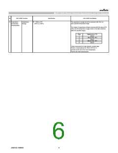
17 Electrical Appearance
Chatacteri- Capacitance
No defects or abnormalities
Within the specified tolerance
Visual inspection.
The capacitance/Q/D.F. should be measured at 25℃ at the
frequency and voltage shown in the table.
zation
Change
D.F.
R7 : 0.025 max.
Char.
R7 10V min.
(C≦10μF)
Item
Frequency
Voltage
1±0.1kHz
1±0.2Vrms
The insulation resistance should be measured with a DC voltage not
I.R.ꢀ25℃
More than 10,000MΩ or 500Ω・F
exceeding the rated voltage at 25℃ and 125℃ within 2min of charging.
(Whichever is smaller)
I.R.ꢀ125℃
More than 1,000MΩ or 10Ω・F
(Whichever is smaller)
No failure should be observed when 250% of the rated voltage is
applied between the terminations for 1 to 5s, provided the
charge/ discharge current is less than 50mA.
Dielectric
Strength
No failure
JEMCGS-00806C
4

 MURATA [ muRata ]