■AEC-Q200 Murata Standard Specification and Test Methods
No
AEC-Q200 Test Item
Specification.
AEC-Q200 Test Method
Pre-and Post-Stress
Electrical Test
1
2
-
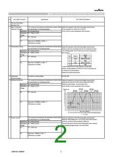
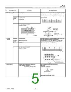
High Temperature
Exposure (Storage)
The measured and observed characteristics should satisfy Solder the capacitor on the test board (glass epoxy board).
the specifications in the following table.
Set the capacitor for 1000±12h at 150±3℃.
Appearance No marking defects
Set for 24±2h at room temperature, then measure.
Capacitance R7 : Within ±10.0%
Change
D.F.
R7 : 0.03 max.
I.R.
More than 10,000MΩ or 500Ω・F
(Whichever is smaller)
3
Temperature Cycling
The measured and observed characteristics should satisfy
the specifications in the following table.
Solder the capacitor on the test board (glass epoxy board).
Perform cycle test according to the four heat treatments listed
in the following table. Set for 24±2 hours at room temperature,
then measure.
Appearance No marking defects
Capacitance R7 : Within ±10.0%
Change
Cycles
Step
Time(min)
D.F.
I.R.
R7 : 0.03 max.
1000
-55℃+0/-3(for R7)
Room
1
2
3
4
15±3
1
15±3
1
More than 10,000MΩ or 500Ω・F
125℃+3/-0(for R7)
Room
(Whichever is smaller)
・ Initial measurement for high dielectric constant type
Perform a heat treatment at 150+0/-10 ℃ for 1h and then set
for 24±2h at room temperature.
Perform the initial measurement.
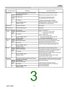
4
5
Destructive
No defects or abnormalities
Per EIA-469.
Physical Analysis
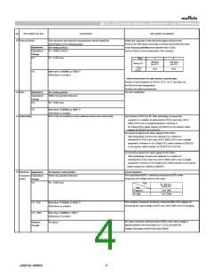
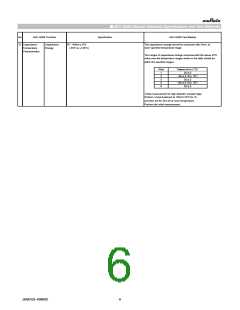
Moisture Resistance
The measured and observed characteristics should satisfy
the specifications in the following table.
Solder the capacitor on the test board (glass epoxy board).
Apply the 24h heat (25 to 65℃) and humidity (80 to 98%)
treatment shown below, 10 consecutive times.
Set for 24±2h at room temperature, then measure.
Appearance No marking defects
Capacitance R7 : Within ±12.5%
Change
Humidity
80~98%
Humidity
80~98%
Temperature
Humidity
90~98%
Humidity
90~98%
Humidity
90~98%
(℃)
70
65
60
55
50
45
40
35
30
25
20
15
10
5
D.F.
I.R.
R7 : 0.03 max.
More than 10,000MΩ or 500Ω・F
+10
2 ℃
(Whichever is smaller)
-
Initial measuremt
0
-5
-10
One cycle 24hours
0
1
2
3
4
5
6
7
8
9
10 11 12 13 14 15 16 17 18 19 20 21 22 23 24
Hours
6
The measured and observed characteristics should satisfy
the specifications in the following table.
Biased Humidity
Solder the capacitor on the test board (glass epoxy board).
Apply the rated voltage and 1.3+0.2/-0vdc (add 6.8kΩ resister)
at 85±3℃ and 80 to 85% humidity for 1000±12h.
Remove and set for 24±2h at room temperature, then measure.
The charge/discharge current is less than 50mA.
Appearance No marking defects
Capacitance R7 : Within ±12.5%
Change
D.F.
R7 : 0.035 max.
I.R.
More than 1,000MΩ or 50Ω・F
(Whichever is smaller)
JEMCGS-00806C
2

 MURATA [ muRata ]