■ Specifications and Test Methods
No Item
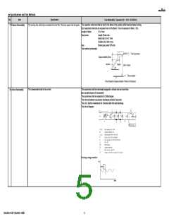
8 Temperature
Specification
Test Method(Ref. Standard:JIS C 5101, IEC60384)
No bias
Nominal values of the temperature coefficientis is
shown in Rated value. But, the Capacitance Change
under Reference Temperature is shown inTable A.
Capacitance Drift: Within +/-1.0% or +/-0.05pF
(Whichever is larger.)
The capacitance change should be measured after 5 min at each specified temp. stage.
Capacitance value as a reference is the value in "*" marked step.
Characteristics of
Capacitance
Capacitance Drift
The capacitance drift is calculated by dividing the differences between the maximum and minimum
measured values in the step 1,3 and 5 by the cap. value in step 3.
Less than 1.0Vrms (Refer to the individual data sheet)
Measurement Voltage
Temperature Step
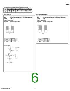
No removal of the terminations or other defect should occur.
Mounting method
Applied Force
Reflow solder the capacitor on the test substrate
10N
9 Adhesive Strength of
Termination
Holding Time
10+/-1s
Applied Direction
In parallel with the test substrate and vertical with the capacitor side
Appearance
Capacitance
Q or D.F.
No defects or abnormalities.
Within the specified initial value.
Within the specified initial value.
Mounting method
Kind of Vibration
Vibration Time
Solder the capacitor on the test substrate
A simple harmonic motion 10Hz to 55Hz to 10Hz
1min
10 Vibration
Total amplitude
1.5mm
Vibration directions and time
This motion should be applied for a period of 2hours in each 3 mutually
perpendicular directions(total of 6hours).
Appearance
Capacitance Change
No defects or abnormalities.
Within +/-0.3pF
Mounting method
Flexure
Holding Time
Reflow solder the capacitor on the test substrate(100×40mm)
1mm
5+/-1s
11 Substrate Bending test
12 Solderability
95% of the terminations is to be soldered evenly and continuously.
Test Method
Flux
Preheat
Kind of Solder
Test Temperature
Test Time
Solder bath method
Solution of rosin ethanol 25(mass)%
80℃ to 120℃、10s to 30s
Sn-3.0Ag-0.5Cu(Lead Free Solder)
245+/-5℃
2+/-0.5s
Immersing in speed
25+/-2.5mm/s
Appearance
Capacitance Change
I.R.
No defects or abnormalities.
Within +/-0.3pF
More than 1000MΩ
Test Method
Solder bath method
Sn-3.0Ag-0.5Cu(Lead Free Solder)
260+/-5℃
10+/-1s
13 Resistance to Soldering
Heat
Kind of Solder
Test Temperature
Test Time
Voltage proof
No defects or abnormalities.
Preheat Temperature
Preheat time
100℃ to 120℃ and 170℃ to 200℃
Each 1 min
Immersing in speed
Post-treatment
25+/-2.5mm/s
Non treatment:Let sit for 24+/-2hours at room temperature, then measure.
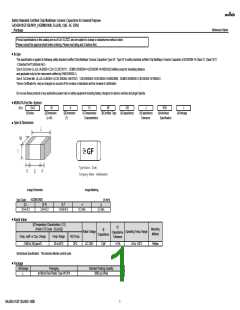
GA342A1XGF120JW31-B0B
3

 MURATA [ muRata ]