• Please read rating and !CAUTION (for storage, operating, rating, soldering, mounting and handling) in this catalog to prevent smoking and/or burning, etc.
• This catalog has only typical specifications because there is no space for detailed specifications. Therefore, please review our product specifications or consult the approval sheet for product specifications before ordering.
!Note
C85E.pdf
Jul.13,2011
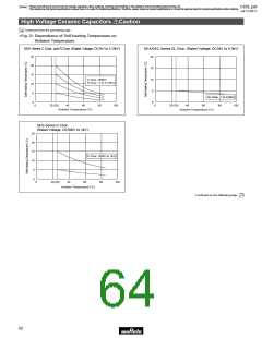
High Voltage Ceramic Capacitors Packaging
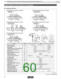
■ Taping Specifications
15.0mm pitch / lead spacing 7.5mm taping
Straight type
15.0mm pitch / lead spacing 7.5mm taping
Vertical crimp type
(Lead Code: P3)
(Lead Code: N3)
∆S
P2
P
D
∆S
D
P2
P
ød
P1
F
ød
P1
F
øD0
øD0
R
P0
R
P0
30.0mm pitch / lead spacing 7.5mm taping
Vertical crimp type
12.7mm pitch / lead spacing 5.0mm taping
Straight type
(Lead Code: N7)
(Lead Code: P2)
P2
P
∆S
∆S
P2
D
D
P
ød
P1
ød
F
P1
F
øD0
øD0
R
P0
P0
R
O
12.7mm pitch / lead spacing 5.0mm taping
Vertical crimp type
(Lead Code: N2)
∆h1
∆h2
T max.
Marked
side
∆S
P2
D
P
ød
P1
F
H0
H0
Lead Code
N2, N3, N7
Lead Code
N3
Lead Code P2, P3
øD0
Except DEF Series
DEF Series
R
P0
Item
Code
P
P3
N3
N7
30.0±2.0
P2
N2
15.0±2.0
15.0±0.3
12.7±1.0
Pitch of component
Pitch of sprocket hole
Lead spacing
P0
F
12.7±0.3
+0.8
–0.2
7.5±1.0
7.5±1.5
3.75±1.0
5.0
P2
P1
D
6.35±1.3
3.85±0.7
Length from hole center to component center
Length from hole center to lead
Body diameter
See the individual product specifications.
11
∆S
W
0±2.0
0±1.0
Deviation along tape, left or right
Carrier tape width
18.0±0.5
W1
H
9.0±0.5
Position of sprocket hole
Lead distance between reference
and bottom planes
+1.5
–1.0
+1.5
20.0
—
—
20.0
—
–1.0
+2.0
+2.0
H0
r
φD0
φd
t1
18.0
—
18.0
–0
–0
+0.5 to -1.0
Protrusion length
4.0±0.1
0.6±0.05
0.6±0.3
Diameter of sprocket hole
Lead diameter
Total tape thickness
t2
1.5 max.
Total thickness, tape and lead wire
Body thickness
T
See the individual product specifications.
+0
L
11.0
Portion to cut in case of defect
Hold down tape width
–1.0
W0
W2
e
11.5 min.
1.5±1.5
Hold down tape position
Coating extension on lead
Deviation across tape, front
Deviation across tape, rear
3.0 max. (Vertical crimp type: Up to the end of crimp)
∆h1
∆h2
2.0 max. 1.0 max.
(in : mm)
Continued on the following page.
58

 MURATA [ muRata ]