• Please read rating and !CAUTION (for storage, operating, rating, soldering, mounting and handling) in this catalog to prevent smoking and/or burning, etc.
• This catalog has only typical specifications because there is no space for detailed specifications. Therefore, please review our product specifications or consult the approval sheet for product specifications before ordering.
!Note
C85E.pdf
Jul.13,2011
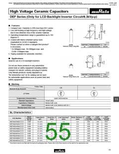
DEF Series (Only for LCD Backlight Inverter Circuit / 6.3kVp-p) Specifications and Test Methods
DEF Series Specifications and Test Methods
No.
1
Item
Specifications
-25 to +105°C
Test Method
Operating Temperature Range
No visible defect, and dimensions are
within specified range.
The capacitor should be visually inspected for evidence of
defect. Dimensions should be measured with slide calipers.
2
3
Appearance and Dimensions
Marking
To be easily legible
The capacitor should be visually inspected.
The capacitor should not be damaged when DC12.6kV is
applied between the lead wires for 1 to 5 sec.
(Charge/Discharge currentV50mA)
Between Lead
Wires
No failure
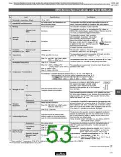
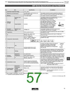
The capacitor is placed in the container
with metal balls of diameter 1mm so that
each lead wire, short circuited, is kept
about 2.0mm off the metal balls as shown
in the figure at right, and DC voltage of
1.3kV is applied for 1 to 5 sec. between
capacitor lead wires and metal balls.
(Charge/Discharge currentV50mA)
Dielectric
Strength
4
Body Insulation
No failure
About
2.0mm
Metal balls
Insulation
Resistance (I.R.) Wires
Between Lead
The insulation resistance should be measured with
DC500±50V within 60±5 sec. of charging.
5
6
7
10000MΩ min.
The capacitance should be measured at 20°C with 1±0.2MHz
and AC5V(r.m.s.) max.
Capacitance
Within specified tolerance
400+20C*2min. (30pF under)
1000 min. (30pF min.)
The Q should be measured at 20°C with 1±0.2MHz and
AC5V(r.m.s.) max.
Q
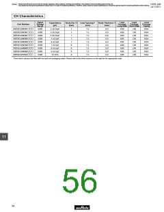
Char. CH: 0±60ppm/°C
Char. SL: +350 to -1000ppm/°C
(Temp. range: +20 to +85°C)
The capacitance measurement should be made at each step
specified in the Table.
8
Temperature Characteristics
Step
1
2
3
4
5
Temp. (°C)
20±2
-25±3
20±2
85±2
20±2
As shown in the figure at right, fix the body of
the capacitor and apply a tensile weight
gradually to each lead wire in the radial
direction of the capacitor up to 10N and keep
it for 10±1 sec.
Pull
W
Lead wire should not be cut off.
Capacitor should not be broken.
9
Strength of Lead
Each lead wire should be subjected to 5N of weight and bent
90° at the point of egress, in one direction, then returned to its
original position and bent 90° in the opposite direction at the
rate of one bend in 2 to 3 sec.
Bending
Appearance
No marked defect
The capacitor should be firmly soldered to the supporting lead
wire and vibrated at a frequency range of 10 to 55Hz, 1.5mm in
total amplitude, with about a 1-minute rate of vibration change
from 10Hz to 55Hz and back to 10Hz. Apply for a total of 6 hrs.,
2 hrs. each in 3 mutually perpendicular directions.
Vibration
Resistance
Capacitance
Q
Within specified tolerance
10
400+20C*2min. (30pF under)
1000 min. (30pF min.)
11
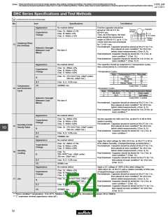
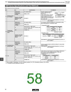
The lead wire of a capacitor should be dipped into a ethanol
solution of 25wt% rosin and then into molten solder for 2±0.5
sec. In both cases the depth of dipping is up to about 1.5 to
2.0mm from the root of lead wires.
Lead wire should be soldered with
11 Solderability of Leads
uniform coating on the axial direction
over 3/4 of the circumferential direction.
Temp. of solder: Lead Free Solder (Sn-3Ag-0.5Cu) 245±5°C
H63 Eutectic Solder 235±5°C
Appearance
No marked defect
The lead wire should be immersed into the melted solder of
350±10°C up to about 1.5 to 2.0mm from the main body for
3.5±0.5 sec.
Post-treatment: Capacitor should be stored for 1 to 2 hrs. at
room condition.*1
Capacitance
Change
Within ±2.5%
Soldering Effect
(Non-Preheat)
12
Dielectric Strength
(Between Lead
Wires)
Per item 4.
*1 "Room condition" Temperature: 15 to 35°C, Relative humidity: 45 to 75%, Atmospheric pressure: 86 to 106kPa
*2 "C" expresses nominal capacitance value (pF).
Continued on the following page.
55

 MURATA [ muRata ]