MP5016 – 2.7V - 15V, 0.7A - 5A, PROGRAMMABLE, CURRENT-LIMITED SWITCH
Table 2: MODE High/Low Digital Voltage
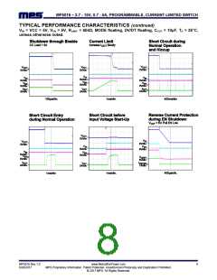
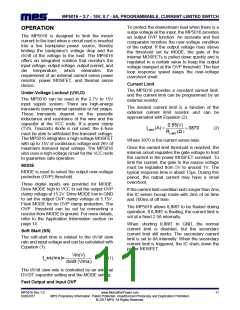
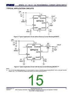
APPLICATION INFORMATION
Setting the Current Limit
Min.
Max.
VMODE_HIGH
VMODE_LOW
VCC - 0.2V
The MP5016 current limit value should exceed
the normal maximum load current, allowing for
tolerances in the current sense value. The
current limit is a function of the external current
limit resistor. Table 1 and Figure 3 list examples
of typical current limit values as a function of the
resistor value.
0.2V
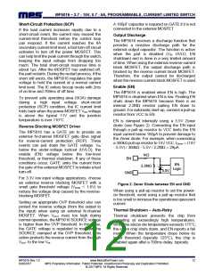
The OVP threshold can also be set by
connecting a resistor from MODE to ground. In
this case, the OVP clamp threshold is given by
Equation (3):
Vclamp (V) 0.047RMODE(KΩ) 0.3(V) (3)
Table 1: Typical Current Limit vs. Current Limit
Resistor (8)
RMODE should be above 68kΩ. For example, an
RMODE value of 76.8kΩ can set the OVP clamp
threshold to 3.9V.
RLIMIT (Ω) 3000 1050 604 470
ILIMIT (A)
0.75 3.5 4.5
422
5
2
NOTE:
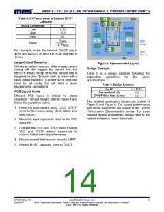
When RMODE is used, place a 39pF capacitor
from MODE to GND.
8) The current limit in Table 1 is a typical value for the reference
design.
Setting the Soft-Start Time
The soft-start time is related to the dV/dt slew
rate and input voltage and can be calculated with
Equation (4):
Vin(V)
(4)
t_ss(ms)
dv/dt (V/ms)
The dV/dt slew rate is controlled by external
DV/DT capacitor setting and MODE setting.
Table 3 shows the dV/dt slew rate when DV/DT
is floating.
Table 3: dV/dt Slew Rate Value when DV/DT is
Floating
Figure 3: Current Limit vs. Current Limit Resistor
The MP5016 current limit can be programmed
from 0.7A to 5A by connecting the correct
resistor (RLIMIT). The current limit cannot be set
too low, because the MP5016 works in sleep
mode when the load is lower than 0.38A,
typically. The current limit logic is disabled in
sleep mode, also.
MODE Connection
dV/dt Slew Rate (V/ms)
Low
High
Float
0.8
2
3.8
Vclamp (V)
RMODE
7ms
For cases with an external DV/DT capacitor, the
dV/dt slew rate can be calculated with Equation
(5):
Setting the Over-Voltage Clamp Threshold
Drive MODE high to VCC to set the output OVP
clamp voltage at 15.2V. Drive MODE low to GND
to set the output OVP clamp voltage at 5.75V.
6.5μΑK1
CDV/DT(nF)
(5)
dv/dt (V/ms)
Refer to Table 2 to set the MODE high/low digital
voltage.
See Table 4 for the K1 factor value.
MP5016 Rev.1.0
6/20/2017
www.MonolithicPower.com
MPS Proprietary Information. Patent Protected. Unauthorized Photocopy and Duplication Prohibited.
© 2017 MPS. All Rights Reserved.
13

 MPS [ MONOLITHIC POWER SYSTEMS ]