MP5016 – 2.7 - 15V, 0.7 - 5A, PROGRAMMABLE, CURRENT-LIMITED SWITCH
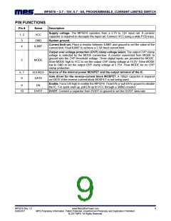
PIN FUNCTIONS
Pin #
Name
Description
Supply voltage. The MP5016 operates from a 2.7V to 15V input rail. A ceramic
capacitor is required to decouple the input rail. Connect VCC using a wide PCB trace.
1, 2
3
VCC
GND
System ground.
Current limit set. Place a resistor between ILIMIT and ground to set the value of the
current limit. Float ILIMIT to achieve a 2.5A fixed current limit.
4
ILIMIT
Output over-voltage protection (OVP) clamp voltage select. The output OVP clamp
voltage is selected by the MODE connection. A resistor connected from MODE to
ground sets the OVP threshold voltage. Three digital inputs are provided for MODE.
Drive MODE high to VCC to set the output OVP clamp voltage at 15.2V. Drive MODE
low to GND to set the output OVP clamp voltage at 5.75V. Float MODE for no OVP
clamp protection.
5
MODE
6, 7
8
SOURCE
GATE
Source of the internal power MOSFET and the output terminal of the IC.
Gate driver for the reverse-current block MOSFET. A 100pF capacitor is required
on GATE if the reverse-current block MOSFET is not being used.
Enable. Force EN high to enable the MP5016. Float EN or pull EN to ground to disable
the IC. For quick start-up, pull EN up to VCC through a 300kΩ resistor.
9
EN
10
DV/DT
DV/DT. Connect a capacitor from DV/DT to ground to set the DV/DT slew rate.
MP5016 Rev.1.0
6/20/2017
www.MonolithicPower.com
MPS Proprietary Information. Patent Protected. Unauthorized Photocopy and Duplication Prohibited.
© 2017 MPS. All Rights Reserved.
9

 MPS [ MONOLITHIC POWER SYSTEMS ]