TM
MP28372 — DUAL 1.5A, 23V, 1.4MHz STEP-DOWN CONVERTER
switch current limit. The inductance value can
be calculated by:
APPLICATION INFORMATION
COMPONENT SELECTION
⎛
⎜
⎝
⎞
⎟
⎟
⎠
VOUT
VOUT
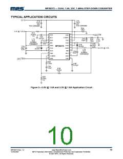
The MP28372 has two channels: A and B. The
following formulas are used for component
selection of both channels. Refer to
components with reference “A” for channel A,
and components with reference “B” for channel
B, respectively, as indicated in Figure 3 (i.e. –
R1A for Channel A and R1B for Channel B).
⎜
L1=
× 1−
fS × ΔIL
V
IN
Where VIN is the input voltage, fS is the
switching frequency, and ΔIL is the peak-to-
peak inductor ripple current.
Choose an inductor that will not saturate under
the maximum inductor peak current.
Setting the Output Voltage
The peak inductor current can be calculated by:
The output voltage is set using a resistive
voltage divider from the output voltage to FB pin.
The voltage divider divides the output voltage
down to the feedback voltage by the ratio:
⎛
⎜
⎝
⎞
⎟
⎟
⎠
VOUT
VOUT
⎜
ILP = ILOAD
+
× 1−
2 × fS × L1
V
IN
Where ILOAD is the load current.
R2
VFB = VOUT
Output Rectifier Diode
R1+ R2
The output rectifier diode supplies the current to
the inductor when the high-side switch is off. To
reduce losses due to the diode forward voltage
and recovery times, use a Schottky diode.
Thus the output voltage is:
R1+ R2
VOUT = 0.92V ×
R2
Choose a diode whose maximum reverse
voltage rating is greater than the maximum
input voltage, and whose current rating is
greater than the maximum load current.
Where VFB is the feedback voltage and VOUT is
the output voltage
A typical value for R2 can be as high as 100kꢀ,
but a typical value is 10kꢀ. Using that value, R1
is determined by:
Input Capacitor
The input current to the step-down converter is
discontinuous, therefore a capacitor is required
to supply the AC current to the step-down
converter while maintaining the DC input
voltage. Use low ESR capacitors for the best
performance. Ceramic capacitors are preferred,
but tantalum or low-ESR electrolytic capacitors
may also suffice.
VOUT
R1 = R2× (
− 1)
0.92V
For example, for a 3.3V output voltage, R2 is
10kꢀ, and R1 is 25.9kꢀ.
Inductor
The inductor is required to supply constant
current to the output load while being driven by
the switched input voltage. A larger value
inductor will result in less ripple current that will
result in lower output ripple voltage. However,
the larger value inductor will have a larger
physical size, higher series resistance, and/or
lower saturation current. A good rule for
determining the inductance to use is to allow
the peak-to-peak ripple current in the inductor
to be approximately 30% of the maximum
switch current limit. Also, make sure that the
peak inductor current is below the maximum
Since the input capacitor (C1) absorbs the input
switching current it requires an adequate ripple
current rating. The RMS current in the input
capacitor can be estimated by:
⎛
⎞
⎟
VOUT
VIN
VOUT
VIN
⎜
IC1 = ILOAD
×
× 1−
⎜
⎝
⎟
⎠
The worst-case condition occurs at VIN = 2VOUT
,
where:
ILOAD
IC1
=
2
MP28372 Rev. 1.4
12/10/2007
www.MonolithicPower.com
MPS Proprietary Information. Unauthorized Photocopy and Duplication Prohibited.
© 2007 MPS. All Rights Reserved.
7

 MPS [ MONOLITHIC POWER SYSTEMS ]