MP2007 – 3A, 1.3V-6.0V INPUT, DDR MEMORY TERMINATION REGUALTOR
DETAILED OPERATING DESCRIPTION
VREF
VDDQ
DDQ
REF
Soft-Start
5V
VDRV
DDQ
VDRV
UVLO
DDQ
UVLO
Current
Limiter
VTT
Regulation
& Deadband
Control
VTT
VTT
Current
Limiter
GND
VTTSEN
VTTSEN
VEN
VTTREF
VTTREF
EN
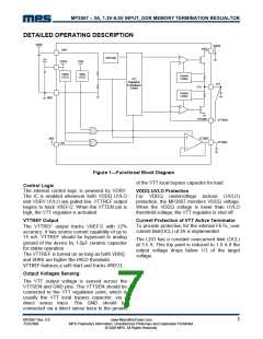
Figure 1—Functional Block Diagram
of the VTT local bypass capacitor for load.
Control Logic
The internal control logic is powered by VDRV.
The IC is enabled whenever both VDDQ UVLO
and VDRV UVLO are pulled low. VTTREF output
begins to track VREF/2. When the VTTEN pin is
high, the VTT regulator is activated.
VDDQ UVLO Protection
For VDDQ undervoltage lockout (UVLO)
protection, the MP2007 monitors VDDQ voltage.
When the VDDQ voltage is lower than UVLO
threshold voltage, the VTT regulator is shut off.
VTTREF Output
Current Protection of VTT Active Terminator
To provide protection for the internal FETs, over
current limit(OCL) of 3A is implemented.
The VTTREF output tracks VREF/2 with ±2%
accuracy. It has source current capability of up to
15 mA. VTTREF should be bypassed to analog
ground of the device by 1.0μF ceramic capacitor
for stable operation.
The VTTREF is turned on as long as both VDDQ
and VDRV are higher the UVLO threshold.
VTTREF features a soft-start and tracks VREF/2.
The LDO has a constant overcurrent limit (OCL)
at 3.5 A. This trip point is reduced to 1.0 A if the
output voltage drops below 1/3 of the target
voltage.
Output Voltages Sensing
The VTT output voltage is sensed across the
VTTSEN and GND pins. The VTTSEN should be
connected to the VTT regulation point, which is
usually the VTT local bypass capacitor, via a
direct sense trace. The GND should be
connected via a direct sense trace to the ground
MP2007 Rev. 0.9
7/23/2009
www.MonolithicPower.com
MPS Proprietary Information. Unauthorized Photocopy and Duplication Prohibited.
© 2009 MPS. All Rights Reserved.
7

 MPS [ MONOLITHIC POWER SYSTEMS ]