MP1527
2A, 1.3MHz
Step-Up Converter
Monolithic Power Systems
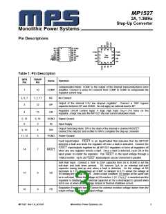
Pin Descriptions
NC
NC
IN
1
2
3
4
5
6
7
14
13
12
11
10
9
SGND
EN
BP
NC
COMP
FB
12
11
10
9
1
2
3
4
COMP
NC
PGND
PGND
SW
SW
Top
View
PGND
SGND
FAULT
BP
8
SS
EN
SW
Table 1: Pin Description
QFN
Pin
TSSOP
Pin
Name
Function
Compensation Node. COMP is the output of the internal transconductance error
amplifier. Connect a series RC network from COMP to SGND to compensate the
regulator control loop.
1
10
COMP
2, 6, 7
3
1, 2, 11
12
NC
BP
No Connect
Output of the internal 2.4V low dropout regulator. Connect a 10nF bypass
capacitor between BP and SGND. Do not apply an external load to BP.
Regulator On/Off Control Input. A logic high input (VEN>1.5V) turns on the
regulator, a logic low puts the MP1527 into low current shutdown mode.
4
13
EN
5, 13
8
6, 14
3
SGND
IN
Signal Ground
Input Supply
Output Switching Node. SW is the drain of the internal n-channel MOSFET.
Connect the inductor and rectifier to SW to complete the step-up converter.
9, 10
4
5
SW
11, 12
PGND
Power Ground
Fault Input/Output.
detected a fault and shuts the regulator off once a fault is indicated. Connect the
input/outputs together for all MP1527 regulators to force all regulators off
is an Input/Output that indicates that the MP1527
FAULT
FAULT
when any one regulator detects a fault. Once a fault is detected, cycle EN or the
input power to restart the regulator. Pull to the input voltage through a
14
7
FAULT
FAULT
input/outputs can be connected in parallel.
100kΩ resistor. Up to 20
FAULT
Soft-Start Input. Connect a 10nF to 22nF capacitor from SS to SGND to set the
soft-start and fault timer periods. SS sources 2µA to an external soft-start
capacitor during start-up and when a fault is detected. As the voltage at SS
increases to 1.2V, the voltage at COMP is clamped to 0.7V above the voltage at
SS limiting the startup current. Under a fault condition, SS ramps at the same rate
15
16
8
9
SS
FB
as in soft-start. When the voltage at SS reaches 1.2V,
is asserted and the
FAULT
regulator is disabled. The external capacitor at SS is discharged to ground when
not in use or when under voltage lockout or thermal shutdown occurs.
Regulation Feedback Input. Connect to external resistive voltage divider from the
output voltage to FB to set output voltage.
MP1527 Rev 1.8_8/31/05
Monolithic Power Systems, Inc.
3

 MPS [ MONOLITHIC POWER SYSTEMS ]