MP1498 – SYNCHRONOUS, STEP-DOWN CONVERTER WITH INTERNAL MOSFETS
APPLICATION INFORMATION
Setting the Output Voltage
Choose an inductor ripple current to be
approximately 30% of the maximum load
current. The maximum inductor peak current is:
The external resistor divider sets the output
voltage (see Typical Application on page 1).
The feedback resistor (R1) sets the feedback
loop bandwidth in conjunction with the internal
compensation capacitor. R2 is then:
IL
IL(MAX) ILOAD
2
Use a larger inductance for improved light-load
efficiency.
R1
R2
V
OUT
1
Selecting the Input Capacitor
0.8V
The input current to the step-down converter is
discontinuous, therefore requires a capacitor
supply the AC current to the step-down
converter while maintaining the DC input
voltage. Use low-ESR capacitors for the best
performance, such as ceramic capacitors with
X5R or X7R dielectrics that have low ESR and
small temperature coefficients. For most
applications, use a 22µF capacitor.
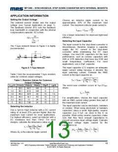
The T-type network shown in Figure 5 is highly
recommended.
Cf
Rt
The input capacitor (C1) requires an adequate
ripple current rating because it absorbs the
input switching current. Estimate the RMS
current in the input capacitor as:
Figure 5: T-Type Network
Table 1 lists the recommended T-type resistors
value for common output voltages.
VOUT
VIN
VOUT
VIN
IC1 ILOAD
1
Table 1: Resistor Values for Common
Output Voltages
VOUT(V) R1(kΩ) R2(kΩ) Rt(kΩ) Cf(pF)
L(µH)
The worst-case condition occurs at VIN=2VOUT
,
where:
1
20.5
30.1
40.2
40.2
40.2
40.2
84.5
61.9
32.4
19.1
13
140
140
59
0
1
1.2
1.8
2.5
3.3
5
0
1
ILOAD
IC1
15
15
15
15
1.5
1.5
2.2
2.2
2
43
For simplification, choose the input capacitor
with an RMS current rating greater than half of
the maximum load current.
24
7.68
24
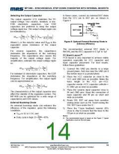
The input capacitor can be electrolytic, tantalum
or ceramic. When using electrolytic or tantalum
capacitors, place a small, high-quality, ceramic
capacitor—e.g. 0.1μF—as close to the IC as
possible. When using ceramic capacitors, make
sure that they have enough capacitance to
prevent excessive input voltage ripple. Estimate
the input voltage ripple caused by the
capacitance as:
Selecting the Inductor
Use a 1µH-to-10µH inductor with a DC current
rating of at least 25% percent higher than the
maximum load current for most applications.
For highest efficiency, select an inductor with a
DC resistance less than 15mꢀ. For most
designs, calculate the inductance value as:
VOUT (V VOUT
)
IN
L1
V IL fOSC
ILOAD
VOUT
VOUT
IN
V
1
IN
fS C1
V
IN
V
IN
Where ΔIL is the inductor ripple current.
MP1498 Rev. 1.01
12/18/2012
www.MonolithicPower.com
MPS Proprietary Information. Patent Protected. Unauthorized Photocopy and Duplication Prohibited.
© 2012 MPS. All Rights Reserved.
13

 MPS [ MONOLITHIC POWER SYSTEMS ]