MP1494 – SYNCHRONOUS STEP-DOWN CONVERTER
0.8
0.7
0.6
0.5
0.4
0.3
0.2
0.1
as possible. When using ceramic capacitors,
make sure that they have enough capacitance to
provide sufficient charge to prevent excessive
voltage ripple at input. The input voltage ripple
caused by capacitance can be estimated by:
V
=3.3V
V
OUT
V
=2.5V
OUT
=5V
OUT
⎛
⎞
⎟
⎠
ILOAD
VOUT
VOUT
ΔV
=
×
× 1−
⎜
IN
V
=1.8V
OUT
fS ×C1
V
IN
V
⎝
IN
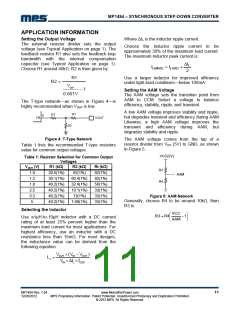
Selecting the Output Capacitor
V
=1.05V
OUT
The output capacitor (C2) maintains the DC
output voltage. Use ceramic, tantalum, or low-
ESR electrolytic capacitors. For best results, use
low ESR capacitors to keep the output voltage
ripple low. The output voltage ripple can be
estimated by:
0
2
4
6
8
10
12
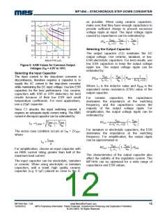
Figure 6: AAM Values for Common Output
Voltages (VIN = 4.5V to 16V)
Selecting the Input Capacitor
⎛
⎞ ⎛
⎞
⎟
⎠
VOUT
VOUT
V
1
The input current to the step-down converter is
discontinuous, therefore requires a capacitor is to
supply the AC current to the step-down converter
while maintaining the DC input voltage. Use low ESR
capacitors for the best performance. Use ceramic
capacitors with X5R or X7R dielectrics for best
results because of their low ESR and small
temperature coefficients. For most applications,
use a 22µF capacitor.
ΔVOUT
=
× 1−
× R
⎟ ⎜
+
⎜
ESR
fS ×L1
8× fS ×C2
⎝
IN ⎠ ⎝
Where L1 is the inductor value and RESR is the
equivalent series resistance (ESR) value of the
output capacitor.
For ceramic capacitors, the capacitance
dominates the impedance at the switching
frequency, and the capacitance causes the
majority of the output voltage ripple. For
simplification, the output voltage ripple can be
estimated by:
Since C1 absorbs the input switching current, it
requires an adequate ripple current rating. The RMS
current in the input capacitor can be estimated by:
⎛
⎞
⎟
⎠
VOUT
8× fS2 ×L1 ×C2
VOUT
⎛
⎞
⎟
VOUT
VIN
VOUT
VIN
ΔVOUT
=
× 1−
⎜
⎜
IC1 = ILOAD
×
× 1−
V
⎜
⎝
⎟
⎠
⎝
IN
For tantalum or electrolytic capacitors, the ESR
dominates the impedance at the switching
frequency. For simplification, the output ripple
can be approximated to:
The worse case condition occurs at VIN = 2VOUT
where:
,
ILOAD
IC1
=
2
VOUT
VOUT
⎛
⎞
ΔVOUT
=
× 1−
×RESR
⎜
⎟
⎠
For simplification, choose an input capacitor with
an RMS current rating greater than half of the
maximum load current.
fS ×L1
V
IN
⎝
The characteristics of the output capacitor also
affect the stability of the regulation system. The
MP1494 can be optimized for a wide range of
capacitance and ESR values.
The input capacitor can be electrolytic, tantalum
or ceramic. When using electrolytic or tantalum
capacitors, add a small, high quality ceramic
capacitor (e.g. 0.1μF) placed as close to the IC
MP1494 Rev. 1.04
12/26/2012
www.MonolithicPower.com
MPS Proprietary Information. Patent Protected. Unauthorized Photocopy and Duplication Prohibited.
© 2012 MPS. All Rights Reserved.
12

 MPS [ MONOLITHIC POWER SYSTEMS ]