MP1494 – SYNCHRONOUS STEP-DOWN CONVERTER
APPLICATION INFORMATION
Setting the Output Voltage
Where ΔIL is the inductor ripple current.
The external resistor divider sets the output
voltage (see Typical Application on page 1). The
feedback resistor R1 also sets the feedback loop
bandwidth with the internal compensation
capacitor (see Typical Application on page 1).
Choose R1 around 40kꢀ. R2 is then given by:
Choose the inductor ripple current to be
approximately 30% of the maximum load current.
The maximum inductor peak current is:
ΔIL
IL(MAX) = ILOAD
+
2
R1
Use a larger inductor for improved efficiency
under light-load conditions—below 100mA.
R2 =
V
OUT
− 1
Setting the AAM Voltage
0.807V
The AAM voltage sets the transition point from
AAM to CCM. Select a voltage to balance
efficiency, stability, ripple, and transient.
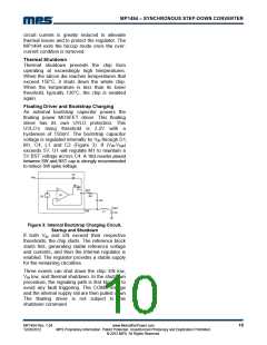
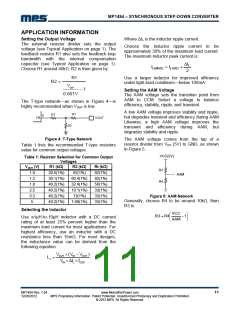
The T-type network—as shown in Figure 4—is
highly recommended when VOUT is low.
A low AAM voltage improves stability and ripple,
but degrades transient and efficiency during AAM.
Likewise, a high AAM voltage improves the
transient and efficiency during AAM, but
degrades stability and ripple.
R1
RT
8
FB
VOUT
R2
Figure 4: T-Type Network
The AAM voltage comes from the tap of a
resistor divider from VCC (5V) to GND, as shown
in Figure 5.
Table 1 lists the recommended T-type resistors
value for common output voltages.
VCC(5V)
Table 1: Resistor Selection for Common Output
Voltages
V
OUT (V)
1.0
1.2
1.8
2.5
3.3
5
R1 (kΩ)
20.5(1%)
30.1(1%)
40.2(1%)
40.2(1%)
40.2(1%)
40.2(1%)
R2 (kΩ)
82(1%)
Rt (kΩ)
82(1%)
82(1%)
56(1%)
33(1%)
33(1%)
33(1%)
R3
AAM
60.4(1%)
32.4(1%)
19.1(1%)
13(1%)
R4
Figure 5: AAM Network
Generally, choose R4 to be around 10kꢀ, then
R3 is:
7.68(1%)
Selecting the Inductor
VCC
AAM
⎛
⎜
⎞
⎠
R3 = R4
−1
⎟
Use a1µH-to-10µH inductor with a DC current
rating of at least 25% percent higher than the
maximum load current for most applications. For
highest efficiency, use an inductor with a DC
resistance less than 15mꢀ. For most designs,
the inductance value can be derived from the
following equation.
⎝
VOUT ×(V − VOUT
)
IN
L1 =
V × ΔIL × fOSC
IN
MP1494 Rev. 1.04
12/26/2012
www.MonolithicPower.com
MPS Proprietary Information. Patent Protected. Unauthorized Photocopy and Duplication Prohibited.
© 2012 MPS. All Rights Reserved.
11

 MPS [ MONOLITHIC POWER SYSTEMS ]