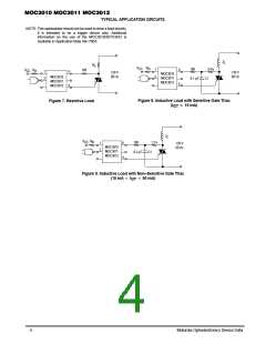
TYPICAL APPLICATION CIRCUITS
NOTE: This optoisolator should not be used to drive a load directly.
It is intended to be a trigger device only. Additional
information on the use of the MOC3010/3011/3012 is
available in Application Note AN–780A.
Z
L
R
L
V
R
in
CC
180
0.1
2.4 k
C1
1
2
6
4
V
R
180
CC in
1
2
6
4
120 V
60 Hz
120 V
60 Hz
MOC3010
MOC3011
MOC3012
MOC3010
MOC3011
MOC3012
µF
Figure 8. Inductive Load with Sensitive Gate Triac
(I 15 mA)
Figure 7. Resistive Load
GT
Z
L
V
R
CC in
180
0.2
1.2 k
C1
1
2
6
4
120 V
60 Hz
MOC3010
MOC3011
MOC3012
µF
Figure 9. Inductive Load with Non–Sensitive Gate Triac
(15 mA 50 mA)
I
GT
4
Motorola Optoelectronics Device Data

 MOTOROLA [ MOTOROLA ]