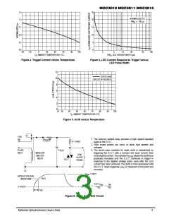
1.5
1.3
25
20
NORMALIZED TO:
PW 100
µ
s
in
1.1
0.9
15
10
0.7
0.5
5
0
–40
–20
0
20
40
60
C)
80
100
1
2
5
10
20
50
100
T , AMBIENT TEMPERATURE (
°
PW , LED TRIGGER WIDTH (µs)
A
in
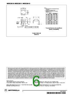
Figure 3. Trigger Current versus Temperature
Figure 4. LED Current Required to Trigger versus
LED Pulse Width
12
10
8
STATIC dv/dt
CIRCUIT IN FIGURE 6
6
4
2
0
25 30
40
50
60
70
80
C)
90
100
T , AMBIENT TEMPERATURE (
°
A
Figure 5. dv/dt versus Temperature
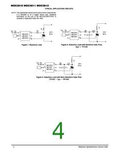
+250
Vdc
1. The mercury wetted relay provides a high speed repeated
pulse to the D.U.T.
R
TEST
R = 10 k
Ω
2. 100x scope probes are used, to allow high speeds and
voltages.
C
PULSE
INPUT
3. The worst–case condition for static dv/dt is established by
triggering the D.U.T. with a normal LED input current, then
TEST
MERCURY
WETTED
RELAY
X100
SCOPE
PROBE
removingthecurrent.ThevariableR
allowsthedv/dttobe
TEST
gradually increased until the D.U.T. continues to trigger in
response to the applied voltage pulse, even after the LED
current has been removed. The dv/dt is then decreased until
D.U.T.
the D.U.T. stops triggering.
recorded.
is measured at this point and
RC
V
= 250 V
max
APPLIED VOLTAGE
WAVEFORM
158 V
0.63 V
max
RC
158
RC
dv dt
0 VOLTS
RC
Figure 6. Static dv/dt Test Circuit
Motorola Optoelectronics Device Data
3

 MOTOROLA [ MOTOROLA ]