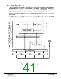
10 Analog-to-Digital Converter
The A/D converter system uses an all capacitive charge redistribution technique to convert analog sig-
nals to digital values. The MC68HC11A8 A/D system is an 8-channel, 8-bit, multiplexed-input, succes-
sive-approximation converter and is accurate to ±1 least significant bit (LSB). It does not require
external sample and hold circuits because of the type of charge redistribution technique used.
Dedicated lines V and V provide the reference supply voltage inputs. Refer to the A/D converter
RH
RL
block diagram.
A multiplexer allows the single A/D converter to select one of 16 analog signals, as shown in the ADCTL
register description.
PE0
AN0
V
RH
8-BIT CAPACITIVE DAC
WITH SAMPLE AND HOLD
PE1
AN1
V
RL
PE2
AN2
SUCCESSIVE APPROXIMATION
REGISTER AND CONTROL
PE3
AN3
RESULT
ANALOG
MUX
PE4
AN4
PE5
AN5
INTERNAL
DATA BUS
PE6
AN6
PE7
AN7
ADCTL A/D CONTROL
RESULT REGISTER INTERFACE
ADR1 A/D RESULT 1
ADR2 A/D RESULT 2
ADR3 A/D RESULT 3
ADR4 A/D RESULT 4
EA9 A/D BLOCK
Figure 13 A/D Converter Block Diagram
MC68HC11A8
MC68HC11A8TS/D
MOTOROLA
41

 MOTOROLA [ MOTOROLA ]