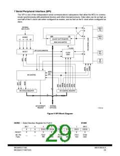
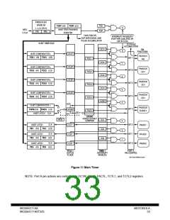
7 Serial Peripheral Interface (SPI)
The SPI is one of two independent serial communications subsystems that allow the MCU to commu-
nicate synchronously with peripheral devices and other microprocessors. Data rates can be as high as
one half of the E-clock rate when configured as master, and as fast as the E clock when configured as
slave.
INTERNAL
MCU CLOCK
MISO
PD2
S
M
MSB
8/16-BIT SHIFT REGISTER
READ DATA BUFFER
LSB
M
S
MOSI
PD3
DIVIDER
÷2 ÷4 ÷16 ÷32
CLOCK
CLOCK
SPI CLOCK (MASTER)
S
SELECT
SCK
PD4
M
LOGIC
SS
PD5
MSTR
SPE
SPI CONTROL
8
SPI STATUS REGISTER
SPI CONTROL REGISTER
8
8
SPI INTERRUPT
REQUEST
INTERNAL
DATA BUS
11 SPI BLOCK
Figure 9 SPI Block Diagram
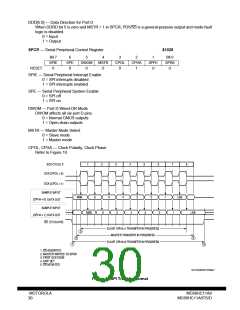
DDRD — Data Direction Register for Port D
$1009
Bit 7
0
6
0
5
DDD5
0
4
DDD4
0
3
DDD3
0
2
DDD2
0
1
DDD1
0
Bit 0
DDD0
0
RESET:
0
0
Alt. Pin
Func.:
__
__
PD5/
SS
PD4/
SCK
PD3/
MOSI
PD2/
MISO
PD1/
TxD
PD0/
RxD
MC68HC11A8
MC68HC11A8TS/D
MOTOROLA
29

 MOTOROLA [ MOTOROLA ]