Freescale SemiconCdhuarcacttoerriz,atIinoncM.easurement Conditions
Device and Signals Set-up
Measurement Set-up
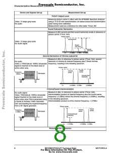
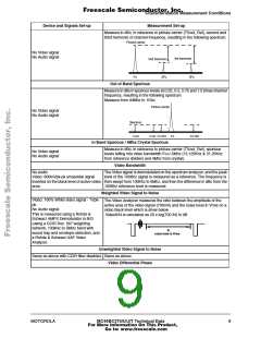
Measure in dBc, in reference to picture carrier (TVout_Ref), second and
third harmonic of channel frequency, resulting in the following spectrum.
Picture carrier
No Video signal
No Audio signal
3rd harmonic
2nd harmonic
Fo
2Fo
3Fo
Out of Band Spurious
Measure in dBuV spurious levels at 0.25, 0.5, 0.75 and 1.5 times channel
frequency, resulting in the following spectrum
Measure from 40Mhz to 1Ghz.
Picture carrier
No Video signal
No Audio signal
Spurious
Fo/4
Fo/2 Fo*3/4
Fo
Fo*3/2
In Band Spurious / 4Mhz Crystal Spurious
Measure in dBc, in reference to picture carrier (TVout_Ref), spurious
levels falling into video bandwidth Fo+/-5Mhz (15.125Khz & 31.25Khz
from reference dividers and 4Mhz from crystal).
No Video signal
No Audio signal
Video Bandwidth
No audio
The Video signal is demodulated on the spectrum analyzer, and the peak
level of the 100Khz signal is measured as a reference. The frequency is
Video: 600mVpk-pk sinusoidal signal
inserted on the black level of active video then swept from 100Khz to 5Mhz, and then the difference in dBc from the
area.
100Khz reference level is measured.
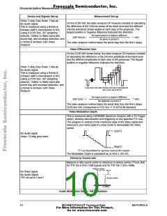
Weighted Video Signal to Noise
Video: 100% White video signal - 1Vpk-
pk.
No Audio signal
The Video Analyzer measures the ratio between the amplitude of the
active area of the video signal (700mV) and the noise level in Vrms on a
video black level which is show below.
This is measured using a Rohde &
Schwarz AMFS Demodulator in B/G
(using a CCIR Rec. 567 weighting
network, 100kHz to 5MHz band with
sound trap and envelope detection, and
a Rohde & Schwarz UAF Video
Analyzer.
VideoS/N is calculated as 20 x log(700 /N) in dB
N
noise level in Vrms
Unweighted Video Signal to Noise
Same as above with CCIR filter disabled. Same as above.
Video Differential Phase
MOTOROLA
MC44BC375/U/J/T Technical Data
For More Information On This Product,
Go to: www.freescale.com
9

 MOTOROLA [ MOTOROLA ]