Freescale Semiconductor, Inc.
Characterization Measurement Conditions
Device and Signals Set-up
Measurement Set-up
Video: 5 step Grey Scale- 1Vpk-pk.
No Audio signal
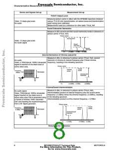
On line CCIR 330, the video analyzer DP measure consists of calculating
the difference of the Chroma phase at the black level and the different
chroma subcarrier phase angles at each step of the greyscale. The
largest positive or negative difference indicates the distortion.
the largest positive or negative difference
This is measured using a Rohde &
Schwarz AMFS Demodulator in B/G
(using a CCIR Rec. 567 weighting
network, 100kHz to 5MHz band with
sound trap, and envelope detection, and
a Rohde & Schwarz UAF Video
Analyzer.
DIFF PHASE =
* 100%
the phase at position 0
The video analyzer method takes the worst step from the first 4 steps.
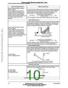
Video Differential Gain
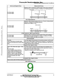
On line CCIR 330 shown below, the video analyzer DG measure consists
of calculating the difference of the Chroma amplitude at the black level
and the different amplitudes at each step of the greyscale. The largest
positive or negative difference indicates the distortion.
Video: 5 step Grey Scale- 1Vpk-pk.
No Audio signal
This is measured using a Rohde &
Schwarz AMFS Demodulator in B/G
(using a CCIR Rec. 567 weighting
network, 100kHz to 5MHz band with
sound trap and envelope detection, and
a Rohde & Schwarz UAF Video
Analyzer.
3
5
1
0
2
4
5-step Greyscale with Chroma subcarrier superimposed
(not to scale), line CCIR 330.
the largest positive or negative difference
DIFF GAIN
=
* 100%
the amplitude at position 0
The video analyzer method takes the worst step from the first 4 steps.
CCIR line 330 corresponds to FCC line 17 in NTSC/M standard
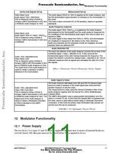
Video Modulation Depth
This is measured using a HP8596E Spectrum Analyzer with a TV Trigger
option, allowing demodulation and triggering on any specified TV Line.
The analyzer is centred on the maximum peak of the Video signal and
reduced to zero Hertz span in Linear mode to demodulate the Video
carrier.
A(
A
m
( 6-10mV)
V
)
No Audio signal
Video: 10 step grey scale
B(mV)
B (0.6 - 3mV)
TV Line Demodulated by Spectrum Analyzer-BG standard
The Modulation Depth is calculated as (A-B)/A x 100 in%
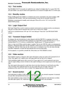
Picture to Sound ratio
Measure in dBc sound carrier in reference to picture carrier (TVout_Ref)
for “PS” bit=0 (PS=12dB typical) and for “PS” bit=1 (PS=16dB),
Picture carrier
No Video signal
No Audio Signal
“PS” bit set to 0 and 1
Sound carrier
Fo
+5.5Mhz
Audio Modulation Depth - FM Modulation
10
MC44BC375/U/J/T Technical Data
For More Information On This Product,
Go to: www.freescale.com
MOTOROLA

 MOTOROLA [ MOTOROLA ]