Freescale Semiconductor, Inc.
2 Device Overview
Device Overview
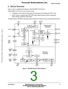
Figure 2 shows a simplified block diagram of the MC44BC375U/J/Tdevice.
The MC44BC375U/J/T device has two main sections:
1. A modulator section which accepts audio and video inputs and modulates the VHF carrier.
2. A PLL section to synthesize the UHF/VHF output channel frequency (from an integrated
UHF oscillator, divided for VHF output)
The high frequency BICMOS technology permits integration of tank circuit and certain filtering functions.
VIDEO
SPLLFLT
LOP
10
8
3
MODULATOR
SECTION
Peak
White Clip
Clamp
AUDIO
TVOVCC
TVOUT
Video
7
6
14
Modulator
31.25kHz
Sound
Oscillator
and FM
Sound
PFD
Audio
Ampli
LPF
PREEM
75Ω
Modulator
13
Prog.
Divider
LPF
ALC
PSS
LPF
VCCA
GND
11
5
Power
save
Psave/
LOP
9
Sound
Modulator
SFS
Test Mode
Divider
Snd Freq
Select
- SFS
16
1
VHF
Divider
VCO & PLL
SECTION
Channel
Select
CHS
-
UHF
OSC.
PLL
PS1/2
Select
- PSS
31.25kHz
Prog.
Divider
Phase
Comp.
Prescaler
/ 8
4Mhz
XCO
Ref Divider
/128
2
CHS
4
XTAL
12
GND
15
PLLFLT
Figure 2. MC44BC375/U/J/T Block Diagram
MOTOROLA
MC44BC375/U/J/T Technical Data
For More Information On This Product,
Go to: www.freescale.com
3

 MOTOROLA [ MOTOROLA ]