Freescale Semiconductor, Inc.
Markings and Case Diagrams
15 Markings and Case Diagrams
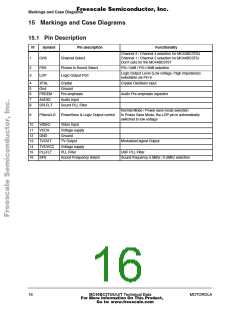
15.1 Pin Description
N°
Symbol
CHS
Pin description
Channel Select
Functionality
Channel 3 / Channel 4 selection for MC44BC375U
Channel 1 / Channel 2 selection for MC44BC375J
Don’t care for the MC44BC375T
1
2
3
PSS
LOP
Picture to Sound Select
Logic Output Port
PS=14dB / PS=16dB selection
Logic Output Level (Low voltage / high impedance)
selectable via Pin 9
4
5
6
7
8
XTAL
Crystal
Crystal Oscillator input
Gnd
Ground
PREEM
AUDIO
SPLFLT
Pre-emphasis
Audio Input
Sound PLL Filter
Audio Pre-emphasis capacitor
Normal Mode / Power save mode selection
In Power Save Mode, the LOP pin is automatically
switched to low voltage
9
PSave/LO
PowerSave & Logic Output control
10
11
12
13
14
15
16
VIDEO
VCCA
GND
Video Input
Voltage supply
Ground
TVOUT
TVOVCC
PLLFLT
SFS
TV Output
Modulated signal Output
Voltage supply
PLL Filter
UHF PLL Filter
Sound Frequency Select
Sound frequency 4.5Mhz / 5.5Mhz selection
16
MC44BC375/U/J/T Technical Data
MOTOROLA
For More Information On This Product,
Go to: www.freescale.com

 MOTOROLA [ MOTOROLA ]