Freescale Semiconductor, Inc.
MC44BC375U Application Schematic
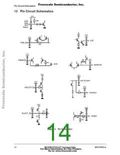
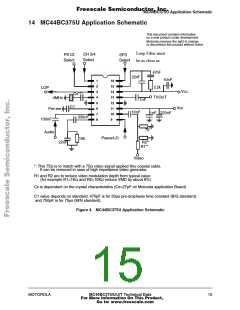
14 MC44BC375U Application Schematic
This document contains information
on a new product under development
Motorola reserves the right to change
or discontinue this product without notice
Loop Filter must
be as close as
CH 3/4
Select
O
PS1/2
Select
SFS
Select
O
O
47nF
22nF
10nF
1
2
3
4
5
6
7
8
16
15
14
13
12
11
10
9
2.2k
LOP
Vcc
Cx***
O
TVOUT
4MHz
Pre-em
100nF
1nF
C1
Vcc
10nF
1nF 220nF
330nF
75*
Audio
O
O
Psave/LO
10k
R2**
R1**
22nF
Video
*: This 75Ω is to match with a 75Ω video signal applied thru coaxial cable.
It can be removed in case of high impedance video generator.
R1 and R2 are to reduce video modulation depth from typical value
(for example R1=1KΩ and R2=10KΩ reduce VMD by about 8%)
Cx is dependant on the crystal characteristics (Cx=27pF on Motorola application Board)
C1 value depends on standard: 470pF is for 50µs pre-emphasis time constant (B/G standard)
and 750pF is for 75µs (M/N standard).
Figure 4. MC44BC375U Application Schematic
MOTOROLA
MC44BC375/U/J/T Technical Data
For More Information On This Product,
Go to: www.freescale.com
15

 MOTOROLA [ MOTOROLA ]