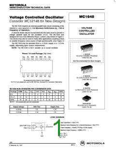
MC1648
V
CC
*
Use high impedance probe (>1.0 Megohm must be used).
** The 1200 ohm resistor and the scope termination impedance constitute
a 25:1 attenuator probe. Coax shall be CT–070–50 or equivalent.
***
**
1
7
14
8
10
12
*** Bypass only that supply opposite ground.
1200
3
L
C
0.1µF
50%
V
P–P
0.1µF
5
t
a
PRF = 1.0MHz
Duty Cycle (Vdc) –
t
t
0.1
µ
F
0.1µF
***
a
b
t
b
Q
≥ 100
L
*
V
EE
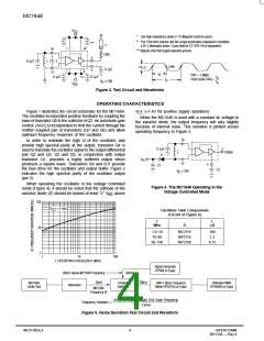
Figure 3. Test Circuit and Waveforms
OPERATING CHARACTERISTICS
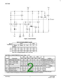
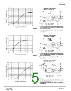
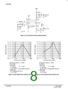
Figure 1 illustrates the circuit schematic for the MC1648.
The oscillator incorporates positive feedback by coupling the
base of transistor Q6 to the collector of Q7. An automatic gain
control (AGC) is incorporated to limit the current through the
emitter–coupled pair of transistors (Q7 and Q6) and allow
optimum frequency response of the oscillator.
V
(≈1.4V for positive supply operation).
EE
When the MC1648 is used with a constant dc voltage to
the varactor diode, the output frequency will vary slightly
because of internal noise. This variation is plotted versus
operating frequency in Figure 5.
10
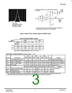
In order to maintain the high Q of the oscillator, and
provide high spectral purity at the output, transistor Q4 is
used to translate the oscillator signal to the output differential
pair Q2 and Q3. Q2 and Q3, in conjunction with output
transistor Q1, provides a highly buffered output which
produces a square wave. Transistors Q9 and Q11 provide
the bias drive for the oscillator and output buffer. Figure 2
indicates the high spectral purity of the oscillator output
(pin 3).
3
0.1µF
L
Output
D
V
in
12
5
C1
C2
Q
≥
100
L
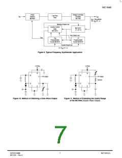
When operating the oscillator in the voltage controlled
mode (Figure 4), it should be noted that the cathode of the
Figure 4. The MC1648 Operating in the
Voltage Controlled Mode
varactor diode (D) should be biased at least “2” V
above
BE
100
V
= 5 Vdc
CC
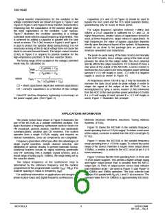
Oscillator Tank Components
(Circuit of Figure 4)
f
L
MHz
D
µH
10
1.0–10
10–60
MV2115
MV2115
MV2106
100
2.3
60–100
0.15
1
1
10
100
f, OPERATING FREQUENCY (MHz)
Signal Generator
HP608 or Equiv
20kHz above MC1648 Frequency
300mV
10mV
20kHz
MC1648
Under Test
Product
Detector
BW=1.0kHz Frequency
Meter HP5210A or Equiv
Voltmeter RMS
HP3400A or Equiv
Attenuator
MC1648
Frequency (f)
(HP5210A output voltage) (Full Scale Frequency)
1.0Volt
Frequency Deviation
Figure 5. Noise Deviation Test Circuit and Waveform
MOTOROLA
4
HIPERCOMM
BR1334 — Rev 4

 MOTOROLA [ MOTOROLA ]