MITSUBISHI MICROCOMPUTERS
3822 Group
SINGLE-CHIP 8-BIT CMOS MICROCOMPUTER
Timer Y
Timer Y is a 16-bit timer that can be selected in one of four modes.
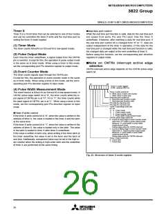
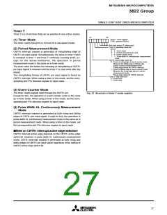
b7
b0
Timer Y mode register
(TYM : address 002816
(1) Timer Mode
The timer counts f(XIN)/16 (or f(XCIN)/16 in low-speed mode).
)
Not used (return “0” when read)
Timer Y operating mode bits
b5 b4
(2) Period Measurement Mode
0
0
1
0 : Timer mode
CNTR1 interrupt request is generated at rising/falling edge of
CNTR1 pin input signal. Simultaneously, the value in timer Y latch
is reloaded in timer Y and timer Y continues counting down. Ex-
cept for the above-mentioned, the operation in period
measurement mode is the same as in timer mode.
1 : Period measurement mode
0 : Event counter mode
1 : Pulse width HL continuously measurement
mode
1
CNTR1 active edge switch bit
0 : Count at rising edge in event counter mode
Measure the falling edge to falling edge
period in period measurement mode
The timer value just before the reloading at rising/falling of CNTR1
pin input signal is retained until the timer Y is read once after the
reload.
Falling edge active for CNTR1 interrupt
1 : Count at falling edge in event counter mode
Measure the rising edge period in period
measurement mode
Rising edge active for CNTR
Timer Y stop control bit
0 : Count start
1 interrupt
The rising/falling timing of CNTR1 pin input signal is found by
CNTR1 interrupt. When using a timer in this mode, set the corre-
sponding port P55 direction register to input mode.
1 : Count stop
(3) Event Counter Mode
The timer counts signals input through the CNTR1 pin.
Except for this, the operation in event counter mode is the same
as in timer mode. When using a timer in this mode, set the corre-
sponding port P55 direction register to input mode.
Fig. 23 Structure of timer Y mode register
(4) Pulse Width HL Continuously Measurement
Mode
CNTR1 interrupt request is generated at both rising and falling
edges of CNTR1 pin input signal. Except for this, the operation in
pulse width HL continuously measurement mode is the same as in
period measurement mode. When using a timer in this mode, set
the corresponding port P55 direction register to input mode.
ꢀNote on CNTR1 interrupt active edge selection
CNTR1 interrupt active edge depends on the CNTR1 active edge
switch bit. However, in pulse width HL continuously measurement
mode, CNTR1 interrupt request is generated at both rising and
falling edges of CNTR1 pin input signal regardless of the setting of
CNTR1 active edge switch bit.
27

 MITSUBISHI [ Mitsubishi Group ]