MITSUBISHI MICROCOMPUTERS
M37270MF-XXXSP
M37270EF-XXXSP, M37270EFSP
SINGLE-CHIP 8-BIT CMOS MICROCOMPUTER with CLOSED CAPTION DECODER
and ON-SCREEN DISPLAY CONTROLLER
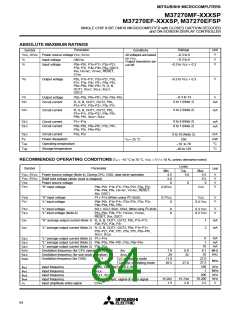
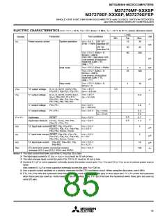
ELECTRIC CHARACTERISTICS (VCC = 5 V ± 10 %, VSS = 0 V, f(XIN) = 8 MHz, Ta = –10 °C to 70 °C, unless otherwise noted)
Limits
Parameter
Test conditions
Unit
Symbol
Min.
Typ.
15
Max.
30
ICC
Power source current
System operation
V
CC = 5.5 V, CRT OFF
f(XIN) = 8 MHz Data slicer OFF
mA
CRT ON
Data slicer ON
30
60
45
VCC = 5.5 V, f(XIN) = 0,
f(XCIN) = 32kHz,
200
OSD OFF, Data slicer OFF,
Low-power dissipation
mode set (CM5 = “0”,
CM6 = “1”)
µA
VCC = 5.5 V, f(XIN) = 8 MHz
Wait mode
Stop mode
2
4
mA
VCC = 5.5 V, f(XIN) = 0,
f(XCIN) = 32kHz,
Low-power dissipation
mode set (CM5 = “0”,
CM6 = “1”)
25
100
µA
VCC = 5.5 V, f(XIN) = 0,
f(XCIN) = 0
1
10
VCC = 4.5 V
IOH = –0.5 mA
2.4
VOH
VOL
“H” output voltage
“L” output voltage
R, G, B, OUT1, OUT2, P03,
P15–P17, P20–P27, P30, P31
V
VCC = 4.5 V
IOL = 0.5 mA
R, G, B, OUT1, OUT2, SOUT,
SCLK, P00–P07, P15–P17,
P20–P27, P50, P32, P47, P56,
P57, P60–P62, P65–P67
0.4
3.0
V
“L” output voltage
“L” output voltage
P30, P31
VCC = 4.5 V
IOL = 10.0 mA
P11–P14
VCC = 4.5 V
IOL = 3 mA
IOL = 6 mA
0.4
0.6
0.7
1.3
0.5
0.5
VT+–VT–
Hysteresis
RESET
VCC = 5.0 V
VCC = 5.0 V
V
Hysteresis (Note 6) HSYNC, VSYNC, P41–P44,
P46, P11–P14, P17
IIZH
IIZL
“H” input leak currentRESET, P03, P10–P17,
VCC = 5.5 V
5
5
µA
µA
P20–P27, P30, P31, P40–P46, VI = 5.5 V
P63, P64, HSYNC, VSYNC
“L” input leak current RESET, P00–P07, P10–P17,
VCC = 5.5 V
P20–P27, P30, P31, P40–P46, VI = 0 V
P63, P64, HSYNC, VSYNC
IIZH
“H” input leak current P00–P02, P04–P07, P50,
P60–P62
VCC = 5.5 V
VI = 12 V
10
µA
2
RBS
I C-BUS·BUS switch connection resistor
VCC = 4.5 V
130
Ω
(between SCL1 and SCL2, SDA1 and SDA2)
Notes 1: The total current that flows out of the IC must be 20 or less.
2: The total input current to IC (IOL1 + IOL2 + IOL3) must be 20 mA or less.
3: The total average input current for ports P30, P31 to IC must be 10 mA or less.
4: Connect 0.1 µF or more capacitor externally across the power source pins VCC–VSS and AVCC–VSS so as to reduce power source
noise.
Also connect 0.1 µF or more capacitor externally across the pins VCC–CNVSS.
5: Use a quartz-crystal oscillator or a ceramic resonator for the CPU oscillation circuit. When using the data slicer, use 8 MHz.
6: P16, P41–P44 have the hysteresis when these pins are used as interrupt input pins or timer input pins. P11–P14 have the hysteresis
2
when these pins are used as multi-master I C-BUS interface ports. P17 and P46 have the hysteresis when these pins are used as
serial I/O pins.
85

 MITSUBISHI [ Mitsubishi Group ]