MITSUBISHI MICROCOMPUTERS
M37270MF-XXXSP
M37270EF-XXXSP, M37270EFSP
SINGLE-CHIP 8-BIT CMOS MICROCOMPUTER with CLOSED CAPTION DECODER
and ON-SCREEN DISPLAY CONTROLLER
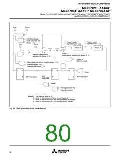
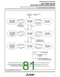
High-speed operation
start mode
Reset
WIT instruction
STP instruction
8MHz oscillating
32kHz oscillating
φ is stopped (“H”)
Timer operating
8MHz oscillating
32kHz oscillating
f( φ ) = 4MHz
8MHz stopped
32kHz stopped
φ is stopped (“H”)
Interrupt
Interrupt (Note 1)
External INT
External INT,
timer interrupt,
or SI/O interrupt
CM7 = 0
CM7 = 1
WIT instruction
Interrupt
STP instruction
8MHz oscillating
32kHz oscillating
φ is stopped (“H”)
Timer operating
(Note 3)
8MHz oscillating
32kHz oscillating
f( φ ) = 16kHz
8MHz stopped
32kHz stopped
φ is stopped (“H”)
Interrupt (Note 2)
CM6 = 0
The program must
allow time for 8MHz
oscillation to stabilize
CM6 = 1
STP instruction
WIT instruction
Interrupt
8MHz stopped
32kHz oscillating
φ is stopped (“H”)
Timer operating
(Note 3)
8MHz stopped
32kHz stopped
φ = stopped (“H”)
8MHz stopped
32kHz oscillating
f( φ ) = 16kHz
Interrupt (Note 2)
CPU mode register
(Address : 00FB16
)
CM
6
7
: Main clock (XIN–XOUT) stop bit
0 : Oscillating
1 : Stopped
CM
: Internal system clock selection bit
0 : XIN-XOUT selected (high-speed mode)
1 : XCIN-XCOUT selected (low-speed mode)
The example assumes that 8 MHz is being applied to the XIN pin and 32 kHz to the XCIN pin. The φ indicates the internal clock.
Notes 1: When the STP state is ended, a delay of approximately 8ms is automatically generated by timer 3 and timer 4.
2: The delay after the STP state ends is approximately 2s.
3: When the internal clock φ divided by 8 is used as the timer count source, the frequency of the count source is 2kHz.
Fig. 94. State transitions of system clock
81

 MITSUBISHI [ Mitsubishi Group ]