Mitsubishi microcomputers
M16C / 61 Group
SINGLE-CHIP 16-BIT CMOS MICROCOMPUTER
Interrupt
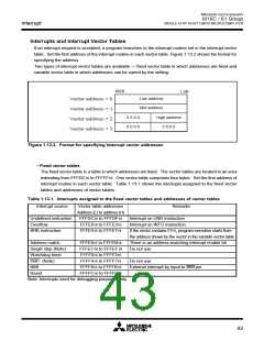
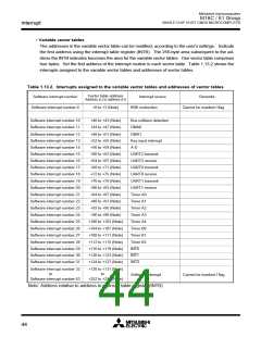
• Variable vector tables
The addresses in the variable vector table can be modified, according to the user’s settings. Indicate
the first address using the interrupt table register (INTB). The 256-byte area subsequent to the ad-
dress the INTB indicates becomes the area for the variable vector tables. One vector table comprises
four bytes. Set the first address of the interrupt routine in each vector table. Table 1.13.2 shows the
interrupts assigned to the variable vector tables and addresses of vector tables.
Table 1.13.2. Interrupts assigned to the variable vector tables and addresses of vector tables
Vector table address
Software interrupt number
Software interrupt number 0
Interrupt source
BRK instruction
Remarks
Address (L) to address (H)
+0 to +3 (Note)
Cannot be masked I flag
Software interrupt number 10
Software interrupt number 11
+40 to +43 (Note)
+44 to +47 (Note)
Bus collision detection
DMA0
Software interrupt number 12
Software interrupt number 13
Software interrupt number 14
Software interrupt number 15
Software interrupt number 16
Software interrupt number 17
Software interrupt number 18
Software interrupt number 19
Software interrupt number 20
Software interrupt number 21
Software interrupt number 22
Software interrupt number 23
Software interrupt number 24
Software interrupt number 25
Software interrupt number 26
Software interrupt number 27
Software interrupt number 28
Software interrupt number 29
Software interrupt number 30
Software interrupt number 31
+48 to +51 (Note)
+52 to +55 (Note)
+56 to +59 (Note)
+60 to +63 (Note)
+64 to +67 (Note)
+68 to +71 (Note)
+72 to +75 (Note)
+76 to +79 (Note)
+80 to +83 (Note)
+84 to +87 (Note)
+88 to +91 (Note)
+92 to +95 (Note)
+96 to +99 (Note)
+100 to +103 (Note)
+104 to +107 (Note)
+108 to +111 (Note)
+112 to +115 (Note)
+116 to +119 (Note)
+120 to +123 (Note)
+124 to +127 (Note)
DMA1
Key input interrupt
A-D
UART2 transmit
UART2 receive
UART0 transmit
UART0 receive
UART1 transmit
UART1 receive
Timer A0
Timer A1
Timer A2
Timer A3
Timer A4
Timer B0
Timer B1
Timer B2
INT0
INT1
INT2
Software interrupt number 32
to
+128 to +131 (Note)
to
Software interrupt
Cannot be masked I flag
Software interrupt number 63
+252 to +255 (Note)
Note: Address relative to address in interrupt table register (INTB)
44

 MITSUBISHI [ Mitsubishi Group ]