Mitsubishi microcomputers
M16C / 61 Group
SINGLE-CHIP 16-BIT CMOS MICROCOMPUTER
Interrupt
Interrupts and Interrupt Vector Tables
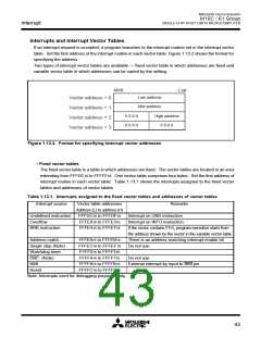
If an interrupt request is accepted, a program branches to the interrupt routine set in the interrupt vector
table. Set the first address of the interrupt routine in each vector table. Figure 1.13.2 shows the format for
specifying the address.
Two types of interrupt vector tables are available — fixed vector table in which addresses are fixed and
variable vector table in which addresses can be varied by the setting.
MSB
LSB
Low address
Mid address
Vector address + 0
Vector address + 1
Vector address + 2
Vector address + 3
0 0 0 0
0 0 0 0
High address
0 0 0 0
Figure 1.13.2. Format for specifying interrupt vector addresses
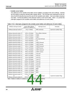
• Fixed vector tables
The fixed vector table is a table in which addresses are fixed. The vector tables are located in an area
extending from FFFDC16 to FFFFF16. One vector table comprises four bytes. Set the first address of
interrupt routine in each vector table. Table 1.13.1 shows the interrupts assigned to the fixed vector
tables and addresses of vector tables.
Table 1.13.1. Interrupts assigned to the fixed vector tables and addresses of vector tables
Interrupt source
Vector table addresses
Address (L) to address (H)
FFFDC16 to FFFDF16
FFFE016 to FFFE316
FFFE416 to FFFE716
Remarks
Undefined instruction
Overflow
Interrupt on UND instruction
Interrupt on INTO instruction
BRK instruction
If the vector contains FF16, program execution starts from
the address shown by the vector in the variable vector table
There is an address-matching interrupt enable bit
Do not use
Address match
FFFE816 to FFFEB16
FFFEC16 to FFFEF16
FFFF016 to FFFF316
FFFF416 to FFFF716
FFFF816 to FFFFB16
FFFFC16 to FFFFF16
Single step (Note)
Watchdog timer
________
DBC (Note)
NMI
Do not use
_______
External interrupt by input to NMI pin
Reset
Note: Interrupts used for debugging purposes only.
43

 MITSUBISHI [ Mitsubishi Group ]