Mitsubishi microcomputers
M16C / 61 Group
Description
SINGLE-CHIP 16-BIT CMOS MICROCOMPUTER
Pin Configuration
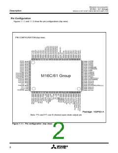
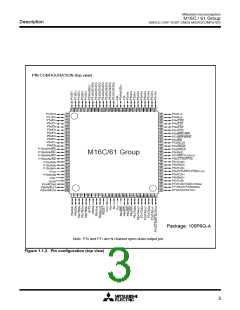
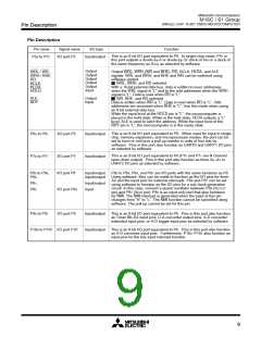
Figures 1.1.1 and 1.1.2 show the pin configurations (top view).
PIN CONFIGURATION (top view)
P07/D7
81
P44/CS0
P45/CS1
P46/CS2
P47/CS3
50
49
48
47
46
45
44
43
42
41
40
39
38
37
36
35
34
33
32
31
P06/D6
82
P05/D5
83
P04/D4
84
P03/D3
P02/D2
P01/D1
85
86
87
88
89
P50/WRL/WR
P51/WRH/BHE
P52/RD
P53/BCLK
P54/HLDA
P55/HOLD
P56/ALE
P57/RDY/CLKOUT
P60/CTS0/RTS0
P61/CLK0
P62/RxD0
P63/TXD0
P64/CTS1/RTS1/CTS0/CLKS1
P65/CLK1
P66/RxD1
P67/TXD1
P00/D0
P107/AN7/KI3
P106/AN6/KI2
P105/AN5/KI1
P104/AN4/KI0
P103/AN3
P102/AN2
P101/AN1
AVSS
P100/AN0
VREF
AVcc
P97/ADTRG
90
91
92
M16C/61 Group
93
94
95
96
97
98
99
100
Package: 100P6S-A
Note: P70 and P71 are N channel open-drain output pin.
Figure 1.1.1. Pin configuration (top view)
2

 MITSUBISHI [ Mitsubishi Group ]