MT9160B/61B
Advance Information
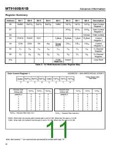
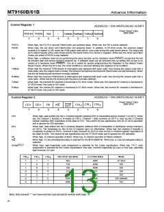
Control Register 1
ADDRESS = 03h WRITE/READ VERIFY
Power Reset Value
0000 0000
_
4
PDFDI PDDR Rst
TxMute RxMute TxBsel RxBsel
7
6
5
3
2
1
0
PDFDI
PDDR
When high, the FDI PLA and the Filter/Codec are powered down. When low, the FDI is active (default).
When high, the ear driver and Filter/Codec are powered down. In addition, in ST-BUS mode, the selected output
channel is tri-stated. In SSI mode the PCM output code will be -zero code during the valid strobe period. The output will
be tri-stated outside of the valid strobe and for the whole frame if no strobe is supplied. When low, the driver and Filter/
Codec are active if PDFDI is low (default).
Rst
When high, a software reset occurs performing the same function as the hardware reset (PWRST) except that the Rst
bit remains high and device remains powered up. A software reset can be removed only by writing this bit low or by
means of a hardware reset (PWRST). This bit is useful for quickly programming the Registers to the default Power
Reset Values. When this bit is low, the reset condition is removed allowing the registers to be modified.
TxMute
When high the transmit PCM stream is interrupted and replaced with quiet code; thus forcing the output code into a
mute state (only the output code is muted, the transmit microphone and transmit Filter/Codec are still functional). When
low the full transmit path functions normally (default).
RxMute
TxBsel
RxBsel
When high the received PCM stream is interrupted and replaced with quiet code; thus forcing the receive path into a
mute state. When low the full receive path functions normally (default).
When high, the transmit B2 channel is functional in ST-BUS mode. When low, the transmit B1 channel is functional in
ST-BUS mode. Not used in SSI mode.
When high, the receive B2 channel is functional in ST-BUS mode. When low, the receive B1 channel is functional in
ST-BUS mode. Not used in SSI mode.
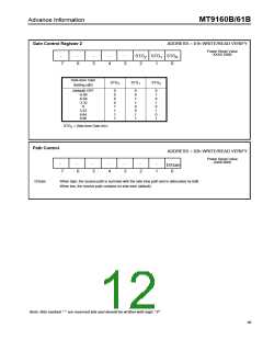
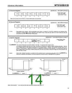
Control Register 2
ADDRESS = 04h WRITE/READ VERIFY
Power Reset Value
Smag/
ITU-T
0000 0010
CSL
1
CSL
CEn
7
DEn
6
D8
5
CSL
2
A/µ
1
0
2
4
3
0
CEn
DEn
When high, data written into the C-Channel register (address 05h) is transmitted during channel 1 on DSTo. When
low, the channel 1 timeslot is tri-stated on DSTo. Channel 1 data received on DSTi is read via the C-Channel
register (address 05h) regardless of the state of CEn. This control bit has significance only for ST-BUS operation
and is ignored for SSI operation.
When high, data written into the D-Channel Register (address 06h) is transmitted (2 bits/frame) during channel 0
on DSTo. The remaining six bits of the D-Channel carry no information. When low, the channel 0 timeslot is
completely tri-stated on DSTo. Channel 0 data received on DSTi is read via the D-Channel register regardless of
the state of DEN. This control bit has significance only for ST-BUS mode and is ignored for SSI operation.
D8
When high, D-channel operates at 8kb/s. When low, D-channel operates at 16kb/s (default).
A/µ
When high, A-Law encoding/decoding is selected for the MT9160B/61B. When low, µ-Law encoding/decoding is
selected.
Smag/ITU-T
When high, sign-magnitude code assignment is selected for the Codec input/output. When low, ITU-T code
assignment is selected for the Codec input/output; true sign, inverted magnitude (µ-Law) or true sign, alternate
digit inversion (A-Law).
CSL
CSL
CSL
0
Bit Clock rate (kHz)
CLOCKin (kHz)
Mode
2
1
1
1
1
0
0
0
0
1
0
0
0
0
1
1
1
0
1
0
1
0
1
N/A
128
4096
4096
4096
512
ST-BUS
SSI
256
SSI
512
SSI
1536
2048
4096
1536
2048
4096
SSI
SSI (default)
SSI
Note: Bits marked "-" are reserved bits and should be written with logic "0"
91

 MITEL [ MITEL NETWORKS CORPORATION ]